Digital radial photography system bulb sport control device

A motion control device and ball tube technology, applied in X-ray equipment, electrical components, computerized tomography scanners, etc., can solve problems such as easy to generate suction noise, manual adjustment, etc., and achieve the effect of eliminating motion noise and reducing work intensity

Inactive Publication Date: 2011-01-26
深圳蓝影医学科技股份有限公司
View PDF0 Cites 0 Cited by
  • Summary
  • Abstract
  • Description
  • Claims
  • Application Information

AI Technical Summary

Problems solved by technology

[0005] The technical problem to be solved by the present invention is to provide a tube motion control device for a digital radiography system, which overcomes the need for an electromagnetic device with a large magnetic force when the tube of a suspended digital radiography system in the prior art is manually rotated around a horizontal axis of rotation. The position of the brake is controlled, which is prone to suction noise and the defect that the relative position between the DR detector and the ball tube needs to be manually adjusted

Method used


Image

  • Digital radial photography system bulb sport control device
  • Digital radial photography system bulb sport control device
  • Digital radial photography system bulb sport control device

Examples


Embodiment Construction

[0019] Below according to accompanying drawing and embodiment the present invention will be described in further detail:

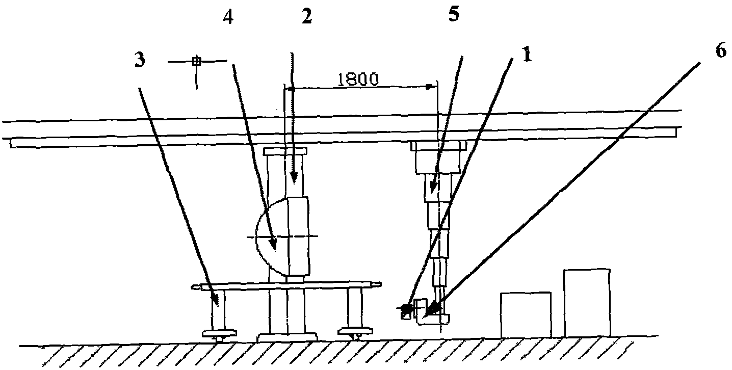
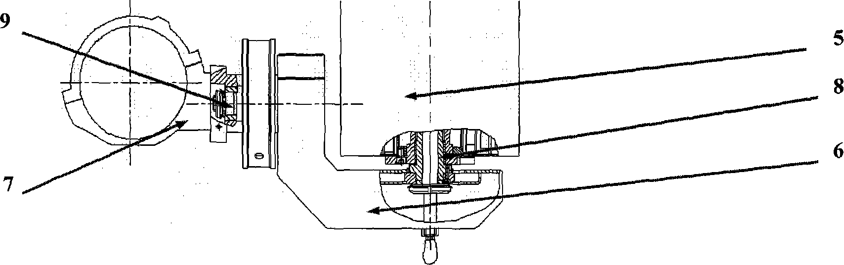
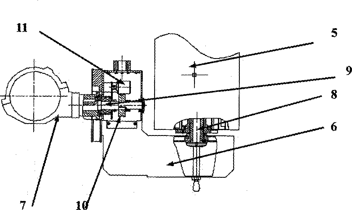
[0020] Such as image 3 , Figure 4 with Figure 5 As shown, the tube motion control device of the digital radiography system of the present invention includes a tube hoop 7, a tube bracket 6 and a horizontal shaft 9 installed on the tube bracket 6, and the tube hoop 7 is fixedly connected to the horizontal shaft 9 , also comprises the motor 12 that is installed on the tube support 6, and motor 12 links to each other with horizontal rotating shaft 9 through a transmission mechanism 10, drives horizontal rotating shaft 9 to rotate by motor 12, thereby drives tube hoop 7 to rotate. It also includes an encoder 11 installed on the tube support 6 and an encoder transmission gear 13 fixedly connected to the horizontal shaft 9. The encoder transmission gear 13 drives the encoder 11 to count the movement of the horizontal shaft 9. The transmission mechanism 10 ...


PUM


Abstract

The invention discloses a bulb tube movement control unit used in a digital radiology photography system, comprising a bulb tube holding hoop, a bulb tube bracket and a horizontal rotating shaft which is arranged on the bulb tube bracket. The bulb tube holding hoop is fixedly connected with the horizontal rotating shaft; the bulb tube movement control unit also comprises a motor arranged on the bulb tube bracket; the motor is connected with the horizontal rotating shaft through an actuating mechanism; the motor drives the horizontal rotating shaft to rotate, thereby driving a bulb tube to rotate. The bulb tube movement control unit used in the digital radiology photography system drives a screw bevel gear mechanism through the motor arranged on the bulb tube bracket, realizes the automatic rotation of the bulb tube around the horizontal rotating shaft, and realizes the automatic tracking of the bulb tube rotating position through an encoder arranged on the bulb tube bracket; the relative position between a DR detector and the bulb tube does not need to be adjusted manually; therefore, the movement noise is eliminated, and the work intensity of doctors is reduced.

Description

technical field [0001] The invention relates to the technical field of medical equipment, in particular to a ball tube motion control device for a digital radiography system. Background technique [0002] Such as figure 1 with figure 2 As shown, the suspended digital radiography system consists of a tube 1 , a column 2 , a high-voltage generator, an image acquisition workstation, an imaging bed 3 , and a DR (Digital Radiography, digital radiography) detector 4 . The tube 1 is installed on the tube hanger 5 through the tube bracket 6, the tube is installed in the tube hoop 7, the tube rotates around the vertical axis 8 and the horizontal axis 9, and can be hung with the tube The telescopic cylinder of frame 5 carries out lifting motion together. The column 2 is installed and fixed on the floor of the machine room, and a DR detector 4 is installed on it. The DR detector 4 can rotate around a horizontal axis, and can also move up and down along the column 2 . The photograp...

Claims


Application Information

Patent Timeline
Patent Type & Authority Patents(China)
IPC IPC(8): A61B6/03H05G1/02
Inventor 王东平
Owner 深圳蓝影医学科技股份有限公司
Why Eureka
Try Eureka