Laboratory cleaning equipment

A cleaning equipment and laboratory technology, applied in lighting and heating equipment, cleaning hollow objects, cleaning methods and utensils, etc., can solve the problem of low cleaning efficiency and achieve the effect of simple and convenient operation

Inactive Publication Date: 2018-10-23
重庆骄直电气有限公司
View PDF2 Cites 4 Cited by
  • Summary
  • Abstract
  • Description
  • Claims
  • Application Information

AI Technical Summary

Problems solved by technology

[0003] The purpose of the present invention is to provide a laboratory cleaning equipment

Method used


Image

  • Laboratory cleaning equipment
  • Laboratory cleaning equipment
  • Laboratory cleaning equipment

Examples


Embodiment Construction

[0018] The present invention will be described in further detail below by means of specific embodiments:

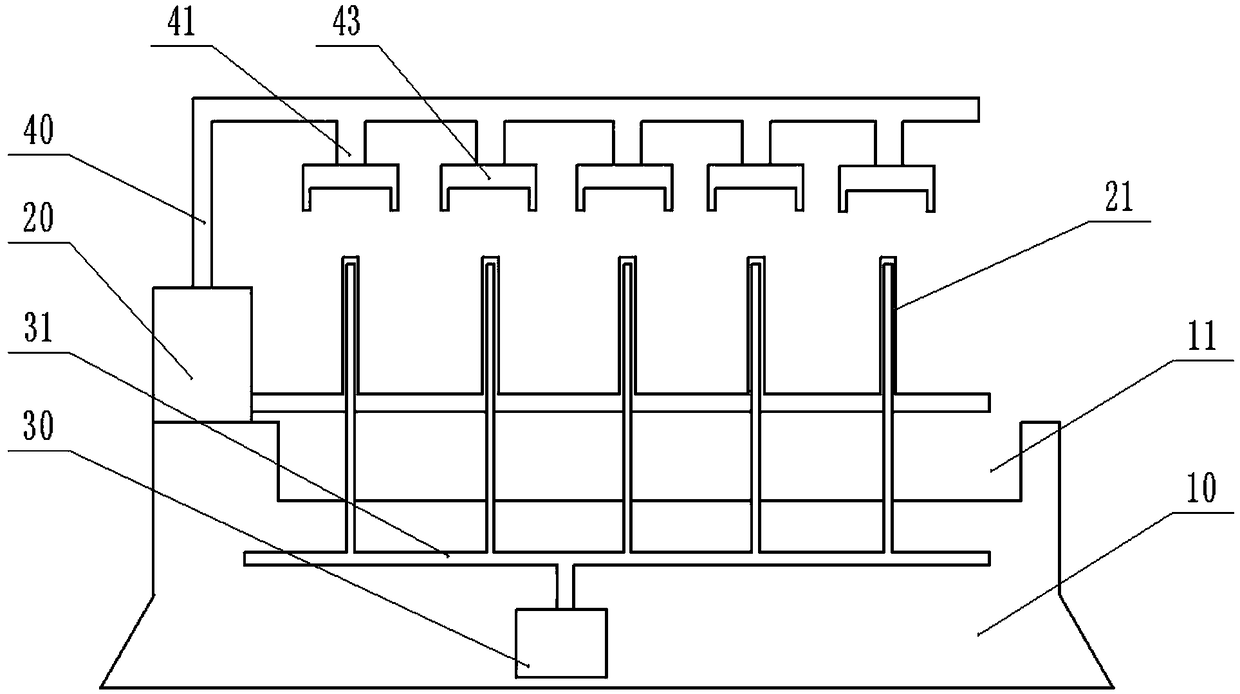
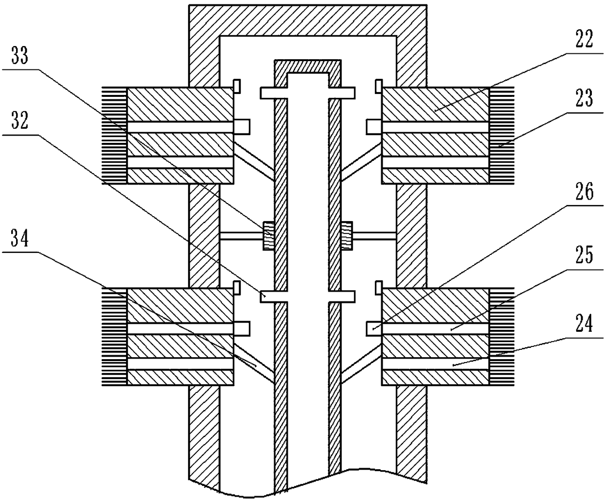
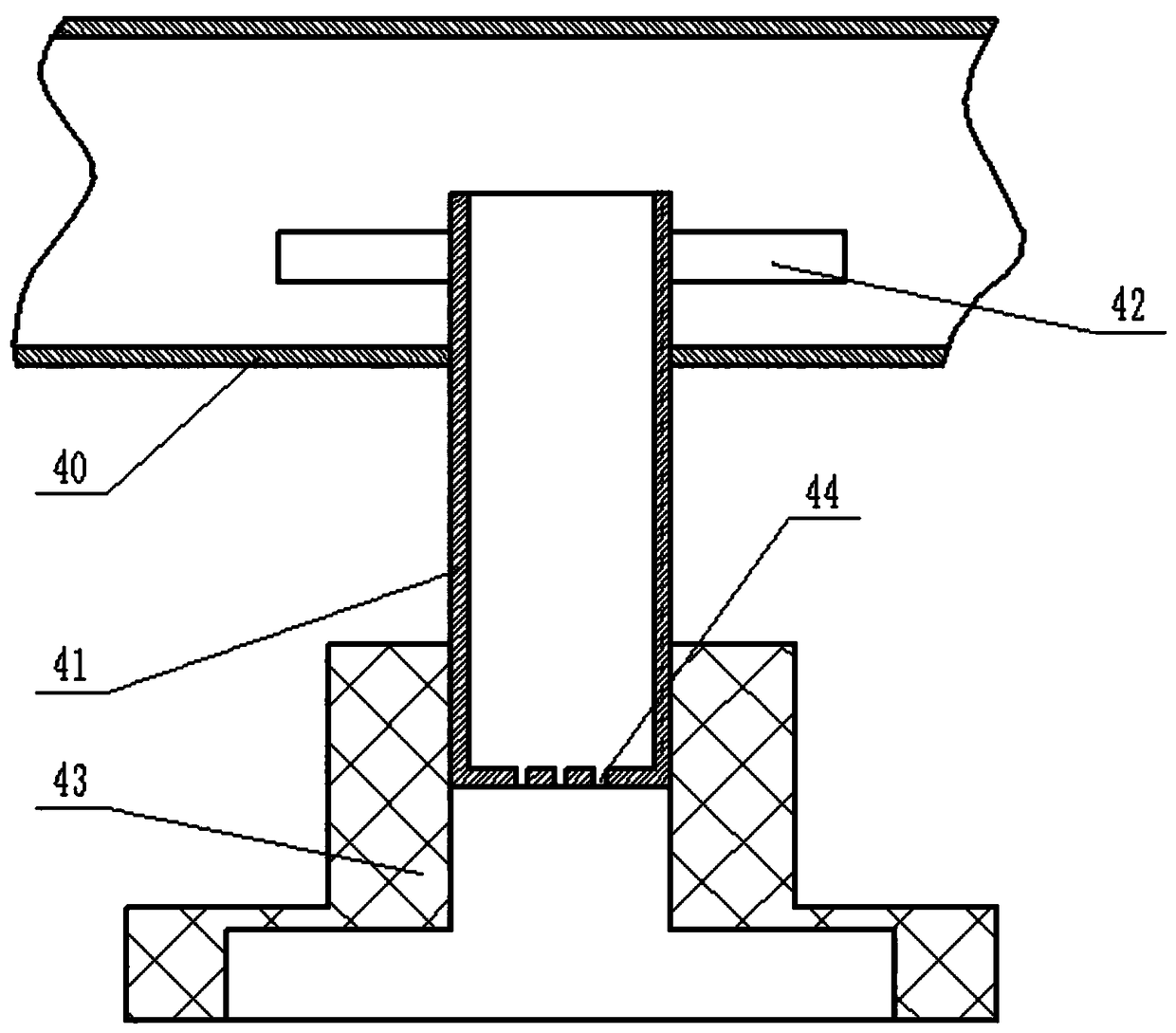
[0019] The reference signs in the drawings of the description include: workbench 10, water tank 11, water tank 20, cleaning pipe 21, cleaning block 22, bristles 23, water outlet 24, air outlet 25, quick female connector 26, hot air box 30, drying Pipeline 31, quick male joint 32, limit ring 33, hinged rod 34, water outlet pipe 40, clamping rod 41, turbine blade 42, elastic jacket 43, spray hole 44.

[0020] Such as figure 1 , figure 2 As shown, the laboratory cleaning equipment of this embodiment includes a workbench 10 on which a water tank 20 and a water tank 11 are arranged. The water tank 20 is provided with a water pump, which is connected with a cleaning pipeline 21. The cleaning pipeline 21 is located above the water tank 11. The side wall of the vertical part on the cleaning pipeline 21 has several side holes, which are slidably connected and sealed. Cleaning ...


PUM


Abstract

The invention belongs to the technical field of cleaning equipment, and particularly discloses laboratory cleaning equipment. The laboratory cleaning equipment comprises a workbench and a cleaning mechanism, wherein the cleaning mechanism comprises a water tank and a cleaning pipeline, the cleaning pipeline communicates with the water tank, a plurality of side holes are formed in the side wall ofthe cleaning pipeline, cleaning blocks are slidably sealed in the side holes, a plurality of bristles are arranged on the outer side walls of the cleaning blocks, water outlet holes are further formedin the cleaning blocks, and the water outlet holes communicate with the cleaning pipeline; the laboratory cleaning equipment further comprises a drying mechanism, wherein the drying mechanism comprises a hot gas box and a drying pipeline, the drying pipeline is vertically and slidably connected to the hot gas box, and a penetrating hole is formed in the lower part of the cleaning pipeline; and the drying pipeline extends into the penetrating hole and is sealed with the penetrating hole, a plurality of quick male connectors are arranged on the side wall of the drying pipeline in a communicating mode, the cleaning blocks are further provided with air outlet holes, and the air outlet holes are provided with quick female connectors matched with the quick male connectors. The laboratory cleaning equipment aims to solve the problem of low cleaning efficiency of experimental instruments such as beakers.

Description

technical field [0001] The invention belongs to the technical field of cleaning equipment, and specifically discloses a laboratory cleaning equipment. Background technique [0002] At present, there are laboratories in enterprises, schools, hospitals and other units, and there are a large number of glassware in the laboratory, such as test tubes, beakers, etc., especially in biochemical laboratories, the utilization rate of these glassware is very high. For test tube utensils, using a test tube brush can clean the test tubes very simply and quickly, but for some medium-sized or large utensils, such as beakers, it is inconvenient to clean manually because the caliber is not enough for people to reach in, but the test tube brush is too large. Small and not easy to clean, so these medium or large utensils are a hassle to clean. Contents of the invention [0003] The object of the present invention is to provide a laboratory cleaning device to solve the problem of low cleanin...

Claims


Application Information

Patent Timeline
IPC IPC(8): B08B9/087B08B9/093F26B21/00
CPCB08B9/0808B08B9/0813F26B21/001
Inventor 任廷军
Owner 重庆骄直电气有限公司
Why Eureka
Try Eureka