Camera shooting device
一种摄像装置、摄像元件的技术,应用在静态摄像机、图像通信、电视等方向,能够解决图像数据画质恶化、噪声增加、摄像元件温度上升等问题
- Summary
- Abstract
- Description
- Claims
- Application Information
AI Technical Summary
Problems solved by technology
Method used
Image

Examples
no. 1 Embodiment approach
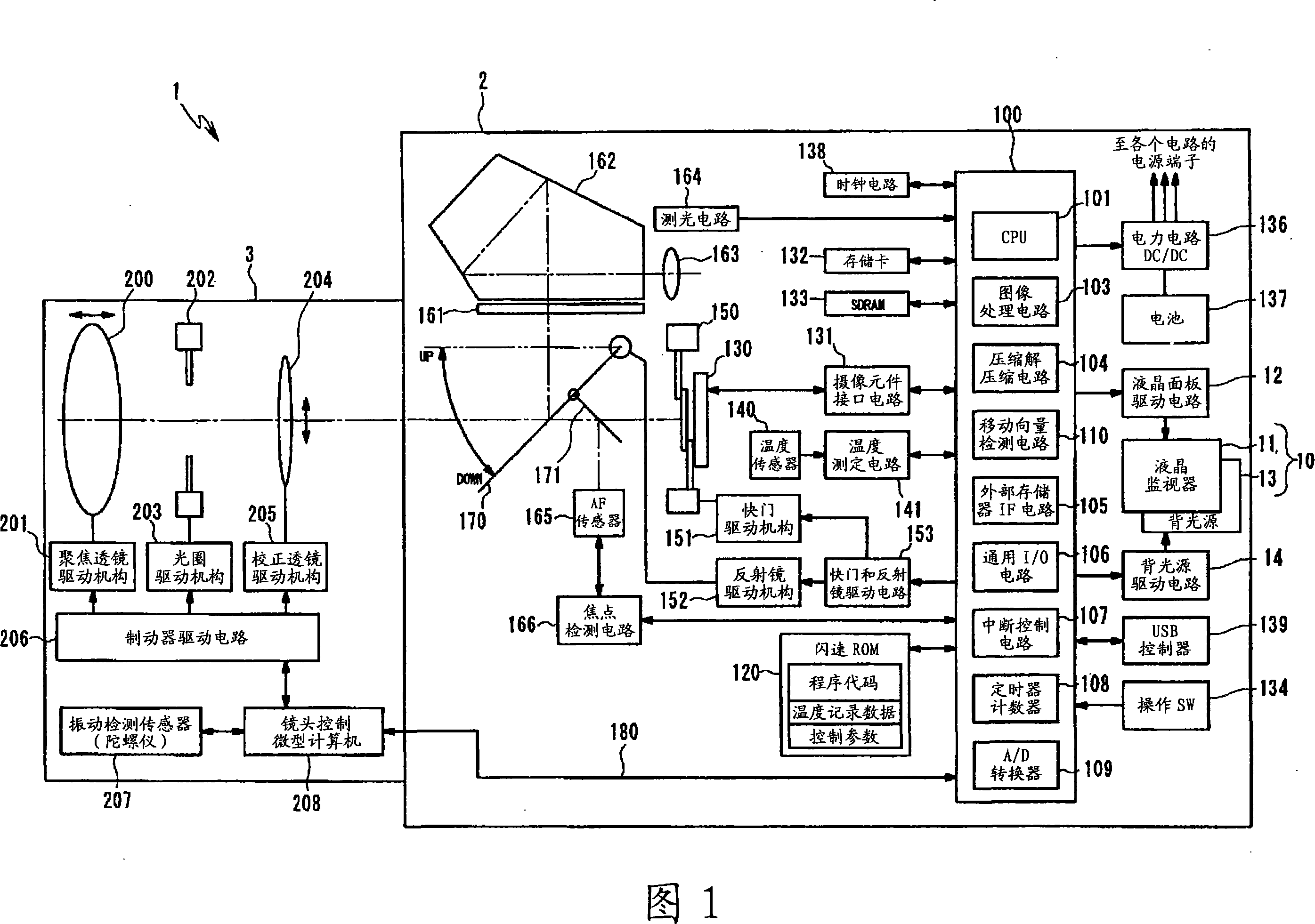
[0033] Hereinafter, a first embodiment of the present invention will be described with reference to FIGS. 1 to 11 . The present embodiment described below is applied to a single-lens reflex (SLR: single-lens reflex) auto focus type still camera (hereinafter referred to as a single-lens reflex camera) with an interchangeable lens as a general imaging device. in the present invention. In addition, electronic still cameras are generally called electronic still cameras, digital still cameras, digital still cameras, and the like.
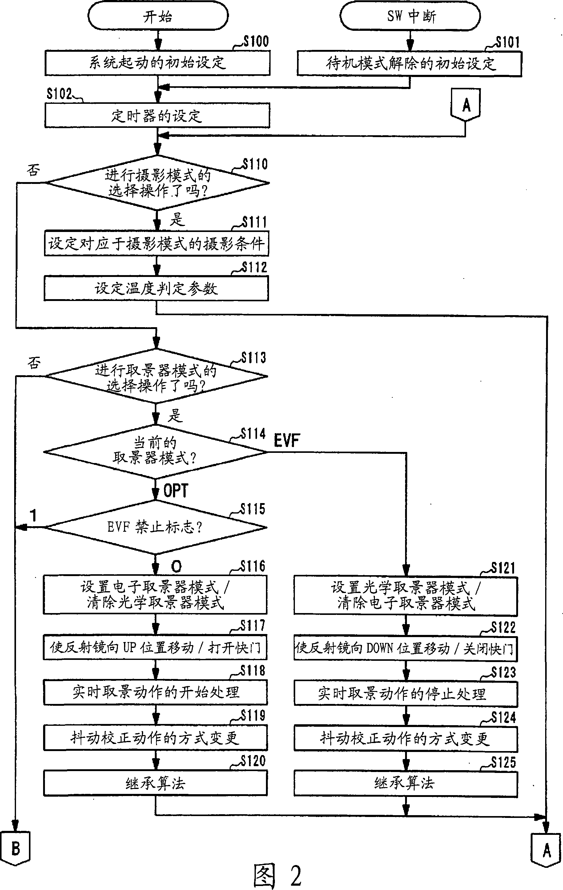
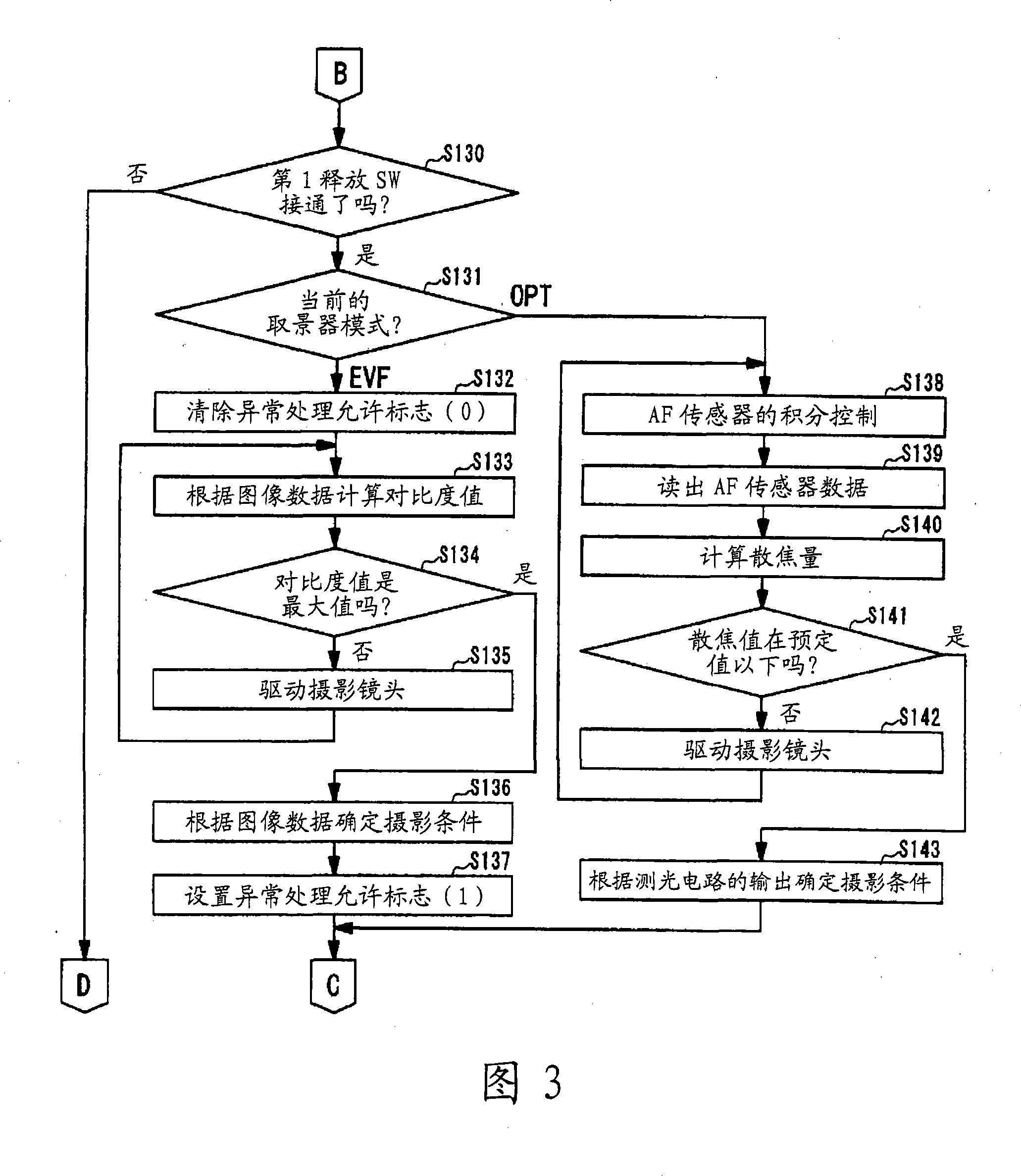
[0034] FIG. 1 is a block diagram showing the main configuration of a single-lens reflex camera. 2 to 5 are flowcharts of the main routine executed in the single-lens reflex camera. Figures 6 and 7 are flowcharts of the timer interrupt routine.
[0035] First, the configuration of the single-lens reflex camera of this embodiment will be described.
[0036] A single-lens reflex camera 1 as an imaging device according to the present embodiment is config...
no. 2 Embodiment approach
[0200] Hereinafter, a second embodiment of the present invention will be described with reference to FIGS. 11 to 18 . The single-lens reflex camera of this embodiment differs from the first embodiment in the means for measuring the noise level of the imaging element. Therefore, only this point of difference will be described, and the same reference numerals will be assigned to the same configurations as those of the first embodiment, and descriptions thereof will be omitted.
[0201] In the above-mentioned first embodiment, by measuring the temperature T of the imaging element 130, the magnitude (noise level) of the noise generated in the imaging element 130 can be indirectly calculated from the previously obtained relationship between the temperature T and the noise level. Then, switching between the OPT mode and the EVF mode is controlled based on the calculated noise level.
[0202] In contrast, in this embodiment, light-shielded optical black (optical black) pixels (herei...
no. 3 Embodiment approach
[0235] Next, a third embodiment of the present invention will be described with reference to FIGS. 19 to 24 .
[0236] The outline of the operation of the first embodiment is as follows: when the temperature of the imaging element exceeds Tth2, if the EVF mode is set, the viewfinder mode is automatically changed from the EVF mode to the OPT mode. Also, setting the EVF mode as the viewfinder mode is prohibited until the temperature of the imaging element reaches Tth1 (
[0237] When the temperature of the imaging element exceeds Tth1 in the state set to the EVF mode, an operation to suppress the temperature rise of the imaging element is performed. That is, the frequency of the clock signal for driving the imaging element is reduced. By reducing the frequency of the clock signal, the frame frequency of the EVF mode will be reduced. Therefore, the amount of image data for one frame read from the imaging eleme...
PUM
 Abstract
Description
Claims
Application Information
 - R&D
- Intellectual Property
- Life Sciences
- Materials
- Tech Scout
- Unparalleled Data Quality
- Higher Quality Content
- 60% Fewer Hallucinations
Browse by: Latest US Patents, China's latest patents, Technical Efficacy Thesaurus, Application Domain, Technology Topic, Popular Technical Reports.
© 2025 PatSnap. All rights reserved.Legal|Privacy policy|Modern Slavery Act Transparency Statement|Sitemap|About US| Contact US: help@patsnap.com