
Electric motor

An electric motor and brush technology, which is applied in the direction of electric components, electrical components, electromechanical devices, etc., can solve the problems of large motor casing, difficult to install noise reduction components, interference, etc., and achieve miniaturization and prevent components from interfering. Effect

Inactive Publication Date: 2008-08-27
AISIN SEIKI KK
View PDF1 Cites 1 Cited by
  • Summary
  • Abstract
  • Description
  • Claims
  • Application Information

AI Technical Summary

Problems solved by technology

[0004] However, in recent years, in-vehicle motors have been miniaturized year by year, and the gaps between the components in the motor case of electric motors have also been minimized.
If noise reduction components are installed inside the motor case, the size of the motor case will increase
Also, if a noise reduction element is to be installed inside the motor, it will inevitably interfere with other components, and it is also faced with the problem that it is difficult to install a noise reduction element in an existing electric motor

Method used


Image

  • Electric motor

Examples


Embodiment Construction

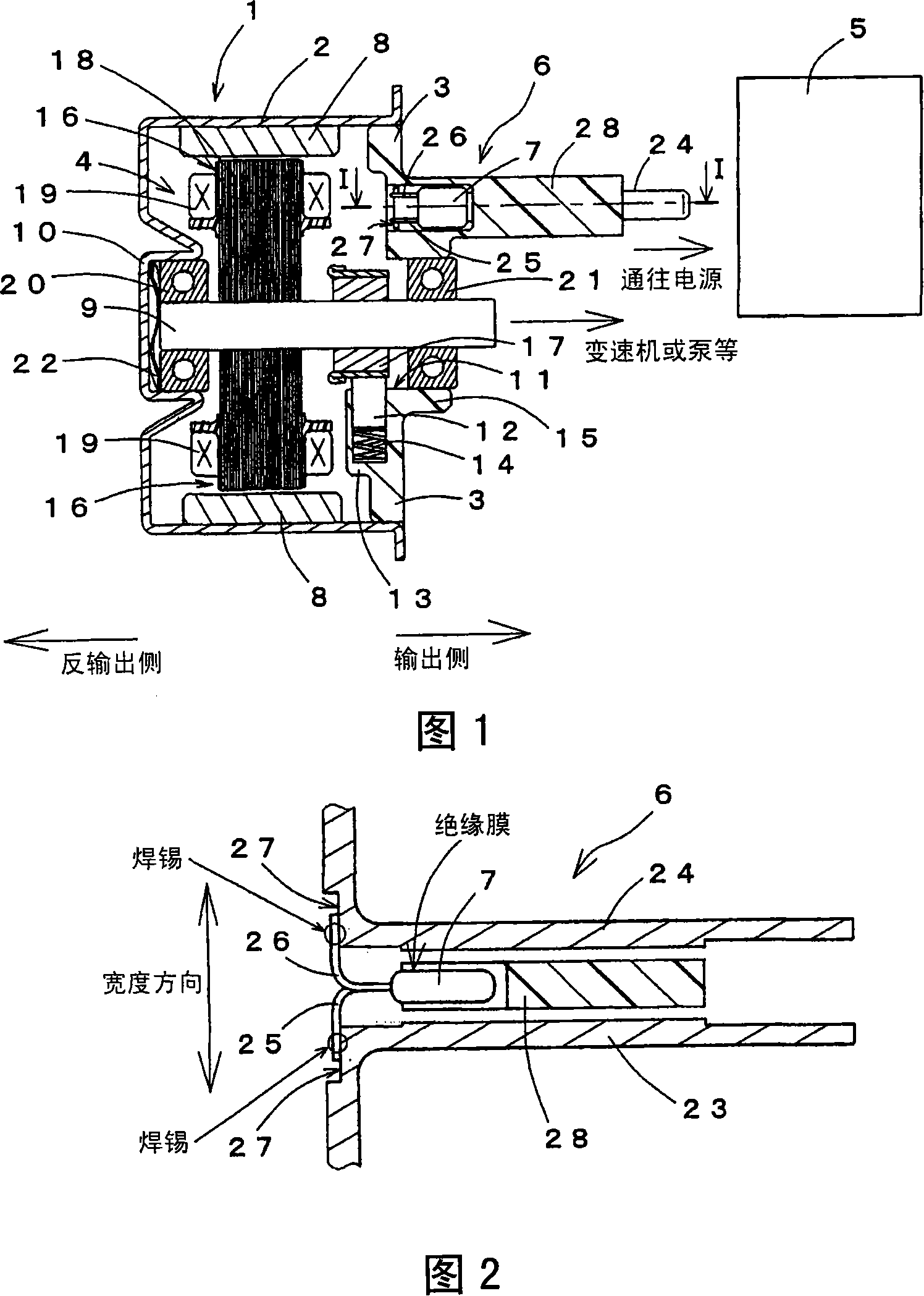
[0021] Hereinafter, a DC electric motor 1 used for automobile parts and the like according to the present invention will be described in detail with reference to FIGS. 1 and 2 .

[0022] FIG. 1 is a sectional view of an electric motor 1 related to the present invention. The electric motor 1 has a substantially bottomed cylindrical motor case 2 opened on the output side, a plate-shaped bottom plate 3 formed to close the opening of the motor case 2 , and a hollow space formed by the motor case 2 and the bottom plate 3 . The rotor 4 within the section, the power supply connector 6 formed on the output side from the power supply 5 to supply power to the rotor 4, and the capacitor 7 (noise reduction element) for noise reduction.

[0023] The motor case 2 is made of metal, and a plurality of magnets 8 are fixed to its inner peripheral surface at equal intervals along the circumferential direction. In addition, a bearing holding portion 10 is integrally formed on the motor housing 2...


PUM


Abstract

The invention provides an electric motor capable of disposing a buzz descending element on a primary electric motor without causing large-scale of the motor housing. The electric motor includes a rotation shaft (9), a commutator (17) fixed to the rotation shaft (9), an armature (16) provided with armature coils (19) electrically connected to the commutator (17), the armature (16) rotatably housed in a motor housing (2), a brush (12) slidably contacting with the commutator (17), a power feeding terminal (6) including two electrode plate (23, 24), and supplying electric power supplied from a power source (5) to the brush (12) and a capacitor (7) provided between the two electrode plate (23, 24) of the power feeding terminal (6).

Description

technical field [0001] The invention relates to an electric motor with noise reducing elements. Background technique [0002] As the prior art related to the present invention, there is an electric motor as described in Patent Document 1. For the electric motor in the prior art, in the power supply circuit that electrically connects the power supply connector and the leaf spring brush, it is provided that the power supply connector is electrically connected through a circuit breaker, and at the same time, the electrical connection between the power supply connector and the leaf spring brush is performed through a choke coil. a distribution board for connection; and a terminal post for electrical connection to the power supply connector and to the leaf spring brushes via the choke coil. The distribution board is electrically connected to the ground post via a capacitor (noise reduction element), and the terminal post is electrically connected to the ground post via a capacit...

Claims


Application Information

Patent Timeline
Patent Type & Authority Applications(China)
IPC IPC(8): H02K11/00H02K11/02H02K13/00H02K5/14
CPCH02K5/225H02K11/026H02K11/024H02K11/028
Inventor 市原流水硲伸一郎
Owner AISIN SEIKI KK
Learn More