
Leakage tripping device for leakage breaker

A technology of leakage circuit breaker and tripping device is applied in the field of assembly structure of leakage tripping device, and can solve the problems of increased space occupied by leakage current circuit breakers, increased external dimensions and the like.

Active Publication Date: 2008-08-27
FUJI ELECTRIC FA COMPONENTS & SYST CO LTD
View PDF1 Cites 4 Cited by
  • Summary
  • Abstract
  • Description
  • Claims
  • Application Information

AI Technical Summary

Problems solved by technology

However, in order to ensure the sufficient space necessary for the assembly and screw fixing of the parts between the parts of the unit case 11 that houses all the parts together, the external dimensions of the case are increased, and the main body case of the earth leakage circuit breaker increased occupied space

Method used


Image

  • Leakage tripping device for leakage breaker
  • Leakage tripping device for leakage breaker
  • Leakage tripping device for leakage breaker

Examples


Embodiment Construction

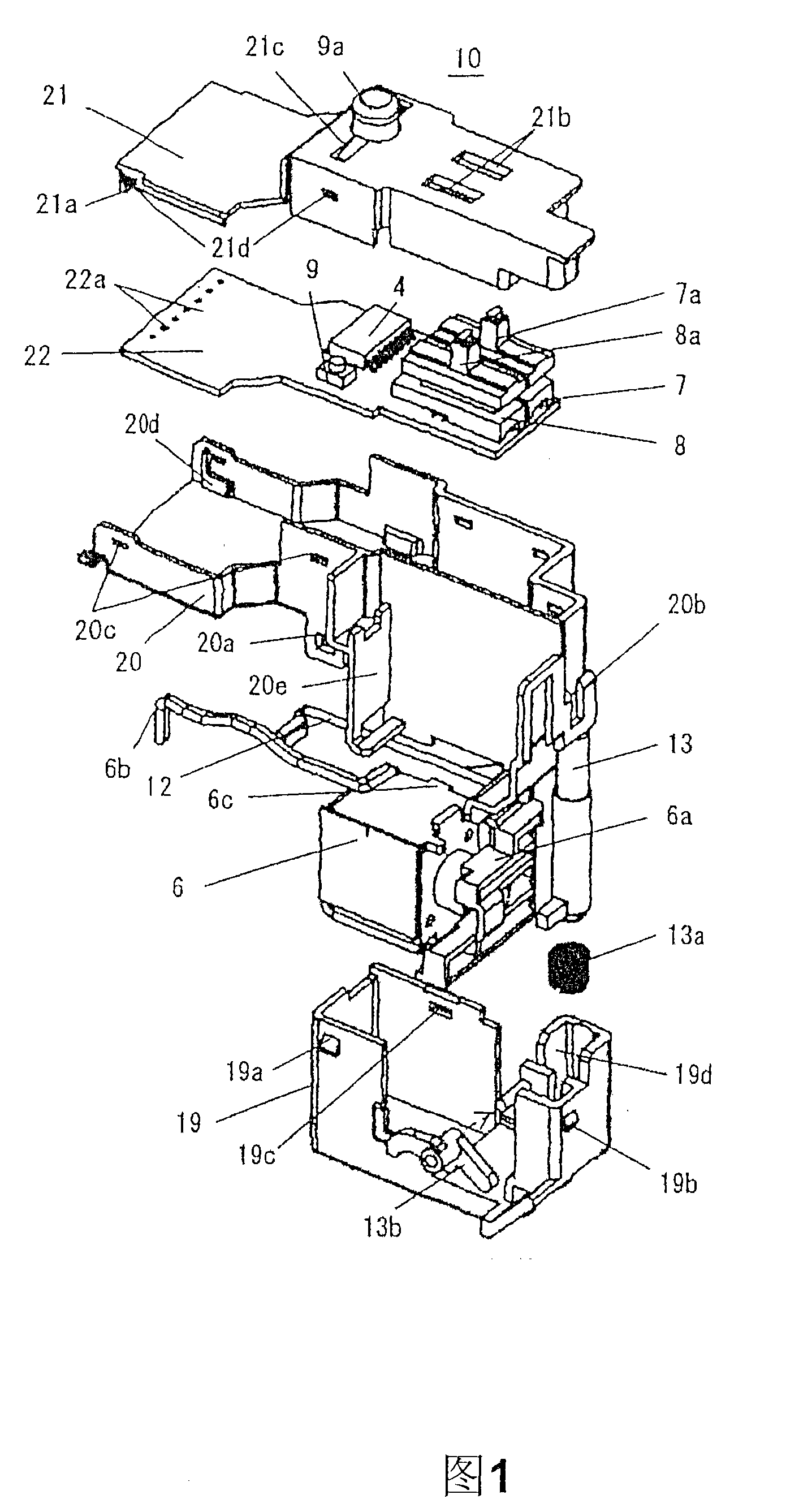
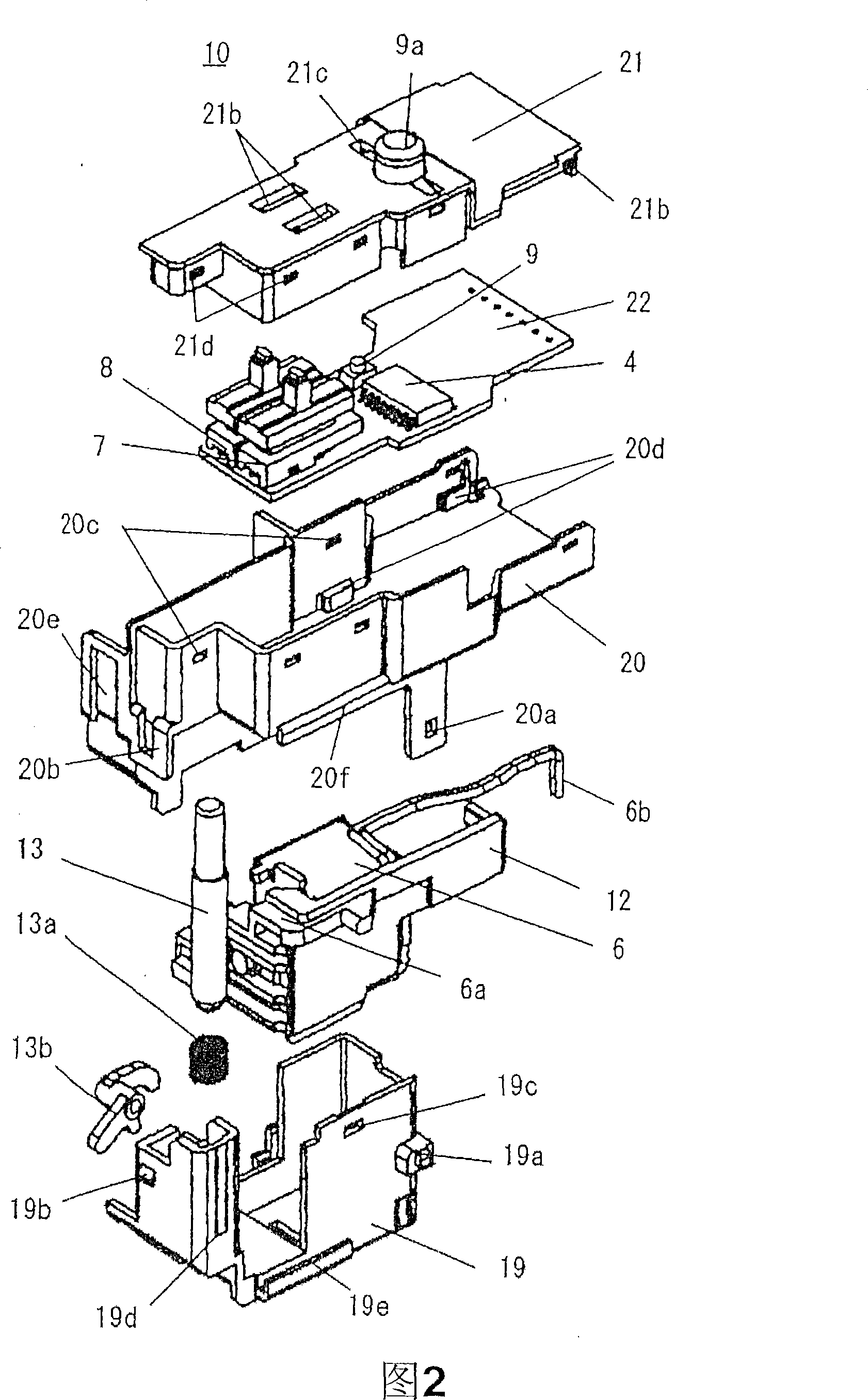
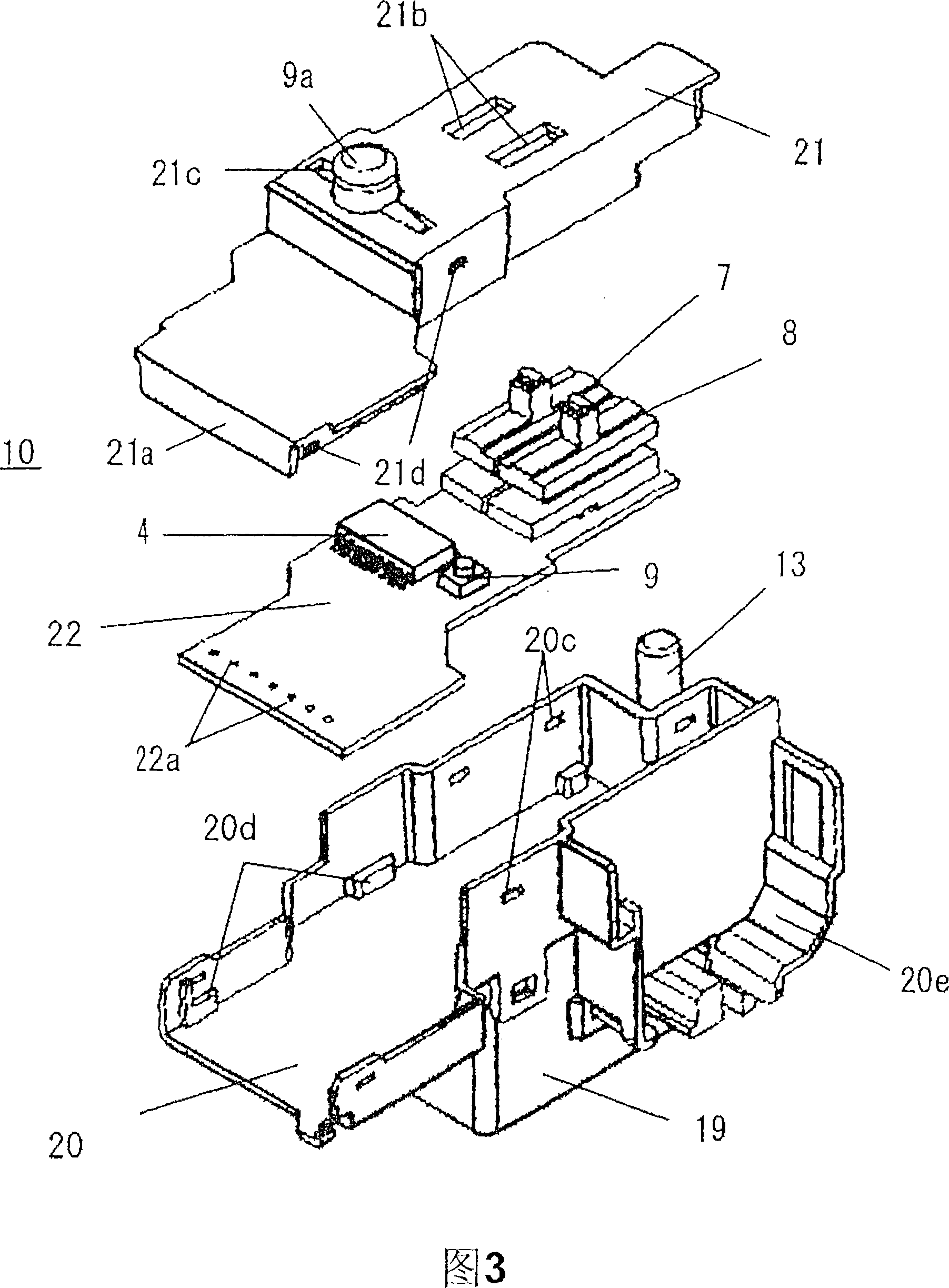
[0070] Hereinafter, embodiments of the present invention will be described based on the examples shown in FIGS. 1 to 6 . In addition, Figures 1 to 3 are exploded perspective views of the leakage tripping device viewed from different directions, and Figures 4(a) to (c) are external views of the assembly method of the leakage tripping device viewed from different directions , Fig. 5 is an exploded perspective view of the whole earth leakage circuit breaker, and Fig. 6 is a plan view showing the internal structure of the state where the intermediate case and the upper cover are removed from the main body case of the earth leakage circuit breaker, and the same as Fig. 7 and Fig. 8 Corresponding components are denoted by the same symbols, and descriptions thereof are omitted.

[0071] First, in Fig. 5 and Fig. 6, 15 is the main body case of the earth leakage circuit breaker which becomes the divided structure of the bottom case 15a, the middle case 15b, and the upper part cover 15c...


PUM


Abstract

The invention provides an earth leakage breaker and an earth leakage unlocking device which can protect the components contained in the shell from influence by the voltaic arc gar, and can simultaneously achieves the space saving and the improved structure in the assembling and improving way. The functional components of the earth leakage detecting circuit (4), the braking coil (6), and the sensitive current switch (7). The action time switch (8), the earth leakage testing switch (9) and the earth leakage displaying button (13) are contained in the cell shell made from the modeling-pressing resin, which are carried in the earth leakage unlocking device of the main body shell of the earth leakage breaker; the cell shell is composed of a two-layer shell composing a lower shell (19), an tray-shaped upper shell (20) overlapped at the lower shell, and a shell cover (21) for covering the upper shell; the lower shell is contained in the braking coil and the earth leakage displaying button; the upper shell is contained with a circuit substrate (22) arranged with the earth leakage detecting circuit, the sensitive current switch, the action time switch, the earth leakage testing switch; base on this, sensitive current switch, the action time switch, the operating potions (7a), (8a), (9a) of the earth leakage testing switch of the circuit substrate traverses the shell cover to protrude outwards.

Description

technical field [0001] The invention relates to an assembly structure of a leakage tripping device mounted on a leakage circuit breaker suitable for a low-voltage power distribution system. Background technique [0002] As is well known, an earth leakage circuit breaker is equipped with an earth fault protection functional part mounted on a main body case together with a current breaking part of a main circuit. The grounding protection functional component is a zero-phase current transformer, a leakage detection circuit (IC) that detects the leakage of the power distribution system according to the secondary output of the zero-phase current transformer, receives the output signal of the leakage detection circuit and controls the opening and closing of the circuit breaker. The trip coil for the tripping operation of the closing mechanism, the switch for adjusting and setting the sensitivity current and action time of the leakage circuit breaker, the leakage test switch, and t...

Claims


Application Information

Patent Timeline
Patent Type & Authority Applications(China)
IPC IPC(8): H01H83/14H01H71/24H01H71/04H01H71/02
CPCH01H83/04H01H71/0207H01H83/06
Inventor 工藤高裕高桥康弘浅野久伸
Owner FUJI ELECTRIC FA COMPONENTS & SYST CO LTD
Learn More