Bistable permanent magnetism hydraulic valve for hydraulic pressure spring operating mechanism

An operating mechanism and hydraulic spring technology, applied to engine components, valve details, multi-way valves, etc., can solve problems such as difficult maintenance, complicated operation process and control oil circuit, and influence on valve action, so as to achieve convenient installation, maintenance and debugging, Reliable anti-leakage oil performance, no effect of refusal or misoperation

Inactive Publication Date: 2008-08-27
SHENYANG POLYTECHNIC UNIV
View PDF0 Cites 6 Cited by
  • Summary
  • Abstract
  • Description
  • Claims
  • Application Information

AI Technical Summary

Problems solved by technology

[0003] (1) Two solenoid valves are required to control the movement of the spool to the left and right respectively, and the operation process and control oil circuit are complicated
[0004] (2) The solenoid valve has high requirements on the cleanliness of the medium, and the medium containing particles is not suitable, and the solenoid valve often refuses to move, which affects the action of the valve.
[0005] (3) There are many sealing links and low safety factor, which is prone to oil leakage
[0006] (4) Difficult maintenance, hydraulic valve spool movement abnormality caused by hydraulic oil pollutant deposition, making the hydraulic valve invalid

Method used


Image

  • Bistable permanent magnetism hydraulic valve for hydraulic pressure spring operating mechanism
  • Bistable permanent magnetism hydraulic valve for hydraulic pressure spring operating mechanism

Examples


Embodiment Construction

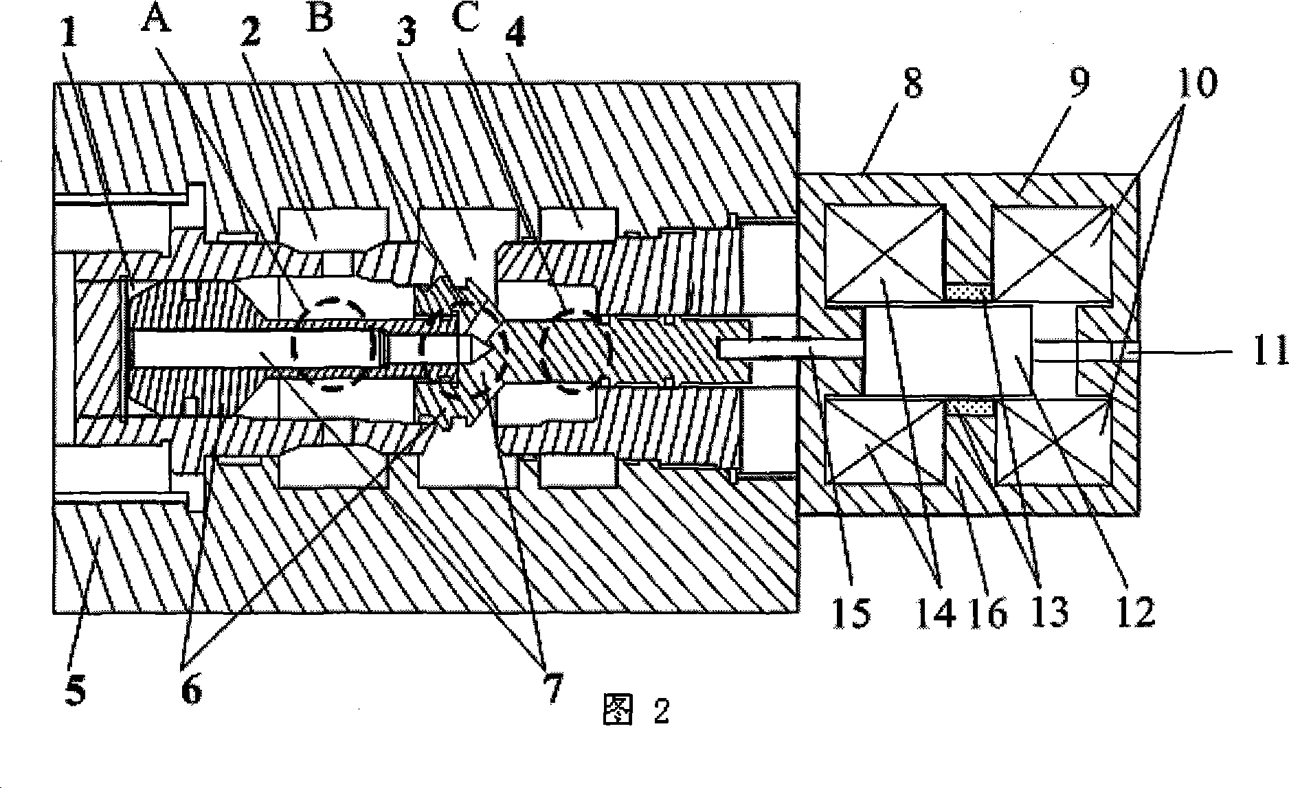
[0014] Embodiments of the present invention are further described below in conjunction with the accompanying drawings: a bistable permanent magnet hydraulic valve for a hydraulic spring operating mechanism, including a valve body 5, which has a normal and low pressure oil zone 2 and a working oil zone 3 , the normal and high pressure oil zone I, the normal and high pressure oil zone II, and the spool 6 located in the valve body 5 are characterized in that: on the right side of the valve body 5, there is a bistable permanent magnet valve 8, and the bistable permanent magnet valve 8 The magnetic valve 8 is provided with a moving iron core 12, and the left connecting rod 15 on the moving iron core 12 is connected with the valve core 6. Among them, the bistable permanent magnet valve 8 includes: a yoke 9, a closing coil 10, a moving iron core 12, a permanent magnet ring 13, and an opening coil 14; wherein: the yoke 9 includes a partition wall 16, and the partition wall 16 left The...


PUM


Abstract

The invention provides a bistable permanent magnet hydraulic valve for a hydraulic spring operation mechanism, belonging to the high pressure breaker switch field; the invention is disclosed aiming at resolving problems existing in the prior hydraulic valve of complicated structure and easy occurrence of refusing operation; the invention consists of a valve body and a permanent magnet valve, wherein the valve body is provided inside with a valve core; the right part of the valve body is provided with a bistable permanent magnet valve which is provided inside with a moving iron core, a driving rod of which is connected with the valve core. The bistable permanent magnet valve comprises a magnetic yoke, a closing coil, the moving iron core, a permanent magnetic ring and a trip coil, wherein the magnetic yoke is provided inside with a separation wall which is provided with the trip coil on the left side, the closing coil on the right side and a permanent magnet in the central part; the central space of the closing coil, the permanent magnet and the trip coil is provided inside with the moving iron core, the left end and the right end of which are provided with a left connecting rod and a right connecting rod respectively; the left connecting rod is connected with the valve core, and the right connecting rod extends out of the magnetic yoke. The lower part of the valve body is provided with oil channels communicated with oil zones in the valve body. The bistable permanent magnet hydraulic valve has the advantages of simple structure, flexible action, safety and reliability and long service life.

Description

technical field [0001] The invention belongs to the technical field of high-voltage circuit breaker operation, in particular to a bistable permanent magnet hydraulic valve used in a hydraulic operating mechanism of a high-voltage circuit breaker. Background technique [0002] At present, the highest working voltage level of circuit breakers for transmission lines is usually 126 ~ 800kV, and hydraulic spring operating mechanisms are widely used on circuit breakers used in this high voltage level. Among them, the hydraulic valve is an important part of the hydraulic spring operating mechanism. There are three solenoid valves on the hydraulic valve, one of the solenoid valves acts when the gate is opened, and the other solenoid valve acts when the gate is closed, and the remaining solenoid valves are spare solenoid valves for opening. Use the on-off control of the solenoid valve to control the oil passage to change the flow direction of the control oil, and then control the mo...

Claims


Application Information

Patent Timeline
Patent Type & Authority Applications(China)
IPC IPC(8): F16K11/044F16K31/08F16K31/06H01H33/34
Inventor 林莘马跃乾李永祥徐建源
Owner SHENYANG POLYTECHNIC UNIV
Why Eureka
Try Eureka