STATCOM-contained line single-end traveling wave distance measurement method based on fault traveling wave line distribution characteristics

A technology of distribution characteristics and fault traveling waves, which is applied in the direction of fault location, measuring electricity, measuring devices, etc., can solve the problems of destroying the impedance uniformity of the entire transmission line and failing to obtain the fault location

Active Publication Date: 2016-08-24
KUNMING UNIV OF SCI & TECH
View PDF5 Cites 6 Cited by
  • Summary
  • Abstract
  • Description
  • Claims
  • Application Information

AI Technical Summary

Problems solved by technology

Since the compensation device in the line destroys the uniformity of the impedance of the transmission line, the single-ended impedance method of power frequency measurement often cannot obtain the correct fault location.

Method used


Image

  • STATCOM-contained line single-end traveling wave distance measurement method based on fault traveling wave line distribution characteristics
  • STATCOM-contained line single-end traveling wave distance measurement method based on fault traveling wave line distribution characteristics
  • STATCOM-contained line single-end traveling wave distance measurement method based on fault traveling wave line distribution characteristics

Examples


Embodiment 1

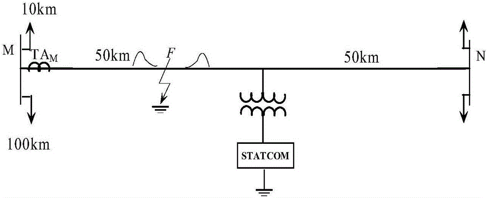
[0098] Example 1: Take figure 1 As an example of the transmission line shown, a ground fault occurred at a distance of 30km from the M terminal on the left side of the STATCOM element.

[0099] According to step one in the manual, obtain the traveling wave data of 1.5l / v time window length at the M terminal; according to step two, use the adjacent sound line current traveling wave and wave impedance to construct the voltage traveling wave to obtain u M = I k ×Z c ; According to step three, calculate the voltage traveling wave and current traveling wave along the line distribution u x,s (x,t) and i x,s (x,t); calculate forward traveling wave and reverse traveling wave u according to step 4 + x,s And u - x,s ;According to step 5, calculate and extract the sudden change of forward traveling wave and reverse traveling wave with And energy with According to step six, construct the ranging function. Get the ranging function f uI (x), f uII (x). According to step seven, obtain the f...

Embodiment 2

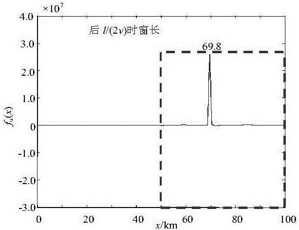
[0100] Example 2: Take figure 1 As an example of the transmission line shown, a ground fault occurs at a distance of 70km from the M terminal on the right side of the TCSC element.

[0101] According to step 1 in the manual, the traveling wave data of 1.5l / v time window length is obtained at the measuring terminal M; according to step 2, the current traveling wave and wave impedance of the adjacent sound line are used to construct the voltage traveling wave to obtain u M = I k ×Z c ; According to step three, calculate the voltage traveling wave and current traveling wave along the line distribution u x,s (x,t) and i x,s (x,t); calculate forward traveling wave and reverse traveling wave u according to step 4 + x,s And u - x,s ;According to step 5, calculate and extract the sudden change of forward traveling wave and reverse traveling wave with And energy with According to step six, construct the ranging function. Get the ranging function f uI (x), f uII (x). According to step ...


PUM


Abstract

The invention relates to a STATCOM-contained line single-end traveling wave distance measurement method based on fault traveling wave line distribution characteristics, and belongs to the technical field of electric power system relay protection. When a line has a fault, a measuring end high-speed collection device obtains measuring end fault current travelling wave data, and voltage travelling waves are constructed by current travelling waves and wave impedance of an adjacent healthy line; secondly, phase-model conversion operation including a faulted phase is carried out to obtain line-model voltage travelling waves and line-model current travelling waves; according to line-model currents and line-model voltages, a Bergeron transmission equation is utilized to calculate the line distribution of voltage and current traveling wave abrupt changes, wherein a line calculation step is 0.1 m; and finally, in time windows [t0, t0+1 / (2v)] and [t0+1 / (2v), t0+1 / v], the absolute values of the traveling wave abrupt changes are calculated and then are integrated to obtain distance measurement functions fuI(x) and fuII(x), and distance measurement of the fault is realized according to the distribution rule of distance measurement function line abrupt changes.

Description

Technical field [0001] The invention relates to a single-ended traveling wave distance measurement method of a STATCOM line containing STATCOM based on the distribution characteristics of the fault traveling wave along the line, and belongs to the technical field of power system relay protection. Background technique [0002] The installation of compensation equipment on UHV transmission lines can enhance the steady-state transmission power capacity of the line and increase the transient stability margin of the system through different compensation methods, optimize line power flow and reduce line losses. Because the line contains a compensation device that destroys the uniformity of the impedance of the entire transmission line, the single-ended impedance method using the power frequency quantity is often unable to obtain the correct fault location. Generally, STATCOM can be regarded as connected to the system through a connecting inductor (usually a transformer), and the output...

Claims


Application Information

Patent Timeline
IPC IPC(8): G01R31/08
CPCG01R31/088
Inventor 束洪春田鑫萃
Owner KUNMING UNIV OF SCI & TECH
Why Eureka
Try Eureka