
Machine for fixing wheels on vehicles

Inactive Publication Date: 2008-08-20
EUROBARNA DE CALDERERIA
View PDF0 Cites 28 Cited by
  • Summary
  • Abstract
  • Description
  • Claims
  • Application Information

AI Technical Summary

Problems solved by technology

[0004] Existing vehicle assembly lines do not have an automated system for placing, securing and assembling vehicle wheels in the manner proposed by the present invention

Method used


Image

  • Machine for fixing wheels on vehicles
  • Machine for fixing wheels on vehicles
  • Machine for fixing wheels on vehicles

Examples


Embodiment Construction

[0038] Description of the preferred embodiment

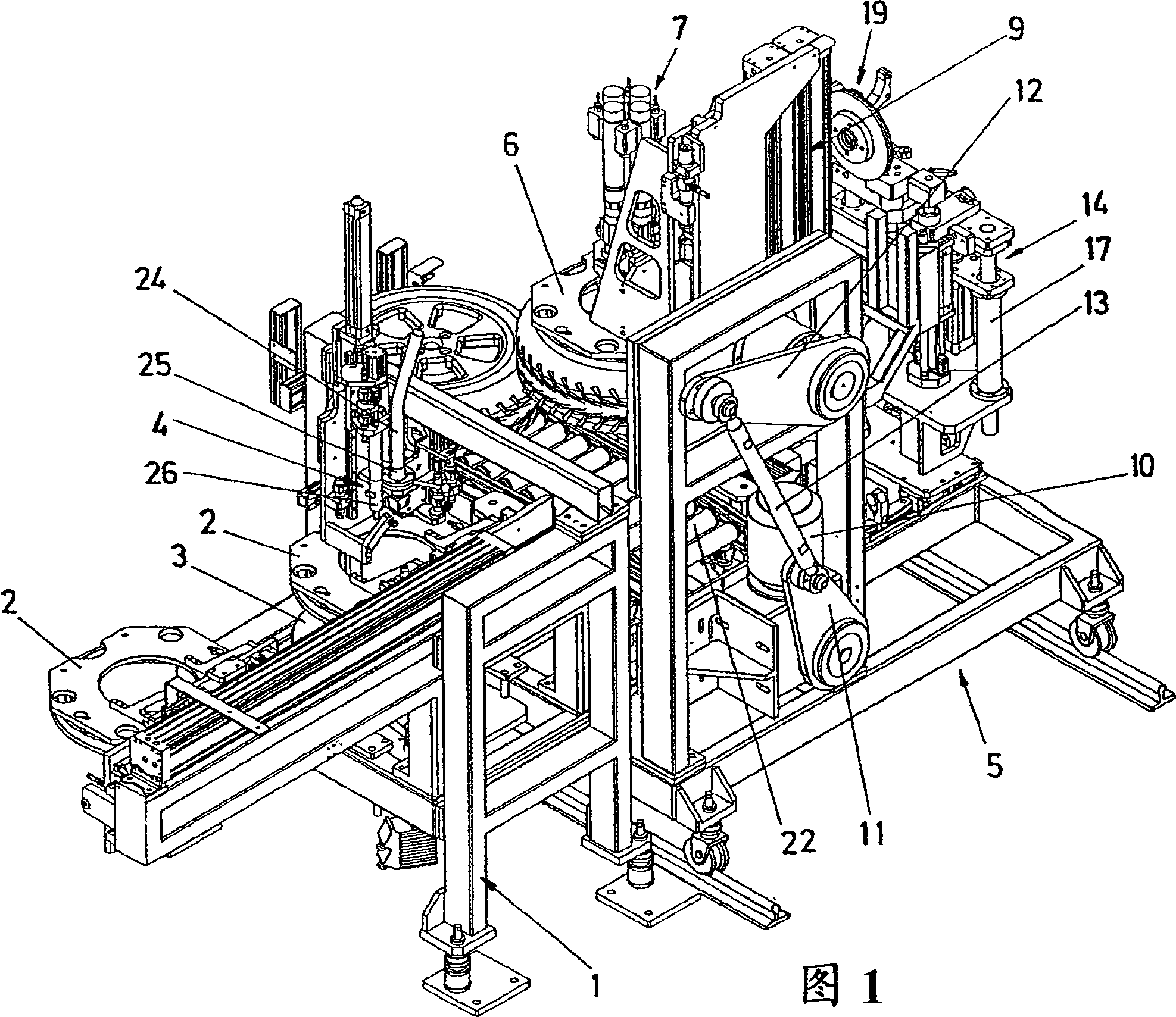
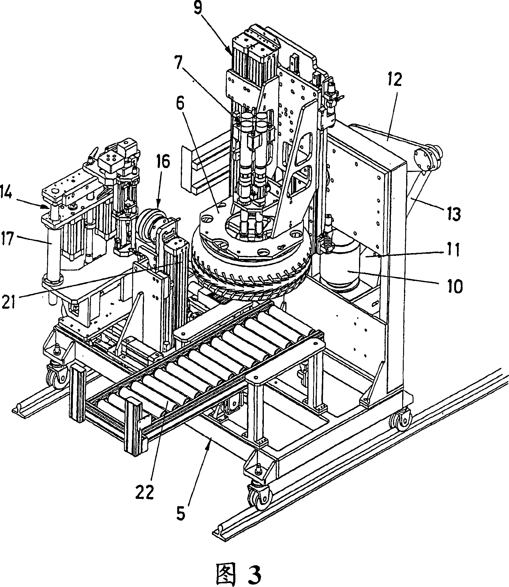
[0039] With reference to the numbered figures listed above, we can see how the object of the invention, functioning as a machine for fastening the wheels to the motor vehicle, provides a base 1 fixed to the ground near the assembly line which transports the vehicles, on which the The wheel is installed automatically. The base 1 receives the wheel onto a positioned centering element that transports the wheel by means of a vertically and horizontally travelable support arm 2 . The arm carries one or more gripping elements which are positioned relative to the tire and have a suction cup effect to effectively grip the wheel.

[0040] Next, the support arm 2 travels horizontally in order to place the wheel on the swivel plate 3 , which is located below the screw supply 4 .

[0041] The rotating plate 3 includes another wheel positioning element operated by means of a photodetector in order to cause the plate 3 to rotate and stop at...


PUM


Abstract

The invention relates to a machine for fastening wheels on a vehicle. The machine of the present invention is capable of mounting and securing wheels to vehicles in a fully automatic manner along an assembly line without the assistance of an operator. The invention consists of a wheel supply base (1) equipped with positioning elements (23) for centering the wheel and lifting the wheel so that the support arm (2) grabs the wheel and transports it to the rotating plate (3), which 3) Incorporated to the screw supply device (4) which is assisted by a light detector to insert the screw into the rim. The support arm (6) adjacent to the mobile base (5) contains a compound screwdriver (7), which is positioned inside the screw. The assembly is then tilted 90° to position the wheel relative to the hub of the vehicle and finally insert the wheel.

Description

[0001] purpose of invention [0002] According to the title of the invention, the invention concerns a machine for the purpose of fastening wheels to a vehicle, and its purpose is to operate in a fully automatic manner as the wheel set (rim and tire set) travels through the assembly line without the intervention of a human operator. way to get them fitted to vehicle wheels or hubs. [0003] The invention is particularly suitable for fitting automotive wheels, although the invention can also be adapted to other types of vehicles once incorporated with appropriate modifications. Background technique [0004] Existing vehicle assembly lines do not have an automated system for placing, securing and assembling vehicle wheels in the manner proposed by the present invention. [0005] The existing system is semi-automatic in that it is accompanied by both human and mechanical operations. The wheels are fixed to the vehicle in two stages, in the first stage the wheel is brought oppos...

Claims


Application Information

Patent Timeline
Patent Type & Authority Applications(China)
IPC IPC(8): B62D65/12B60B29/00B23P19/00B23P19/06
CPCB23P19/069B62D65/12B60B29/00
Inventor M·拉费特菲古拉斯
Owner EUROBARNA DE CALDERERIA
Learn More