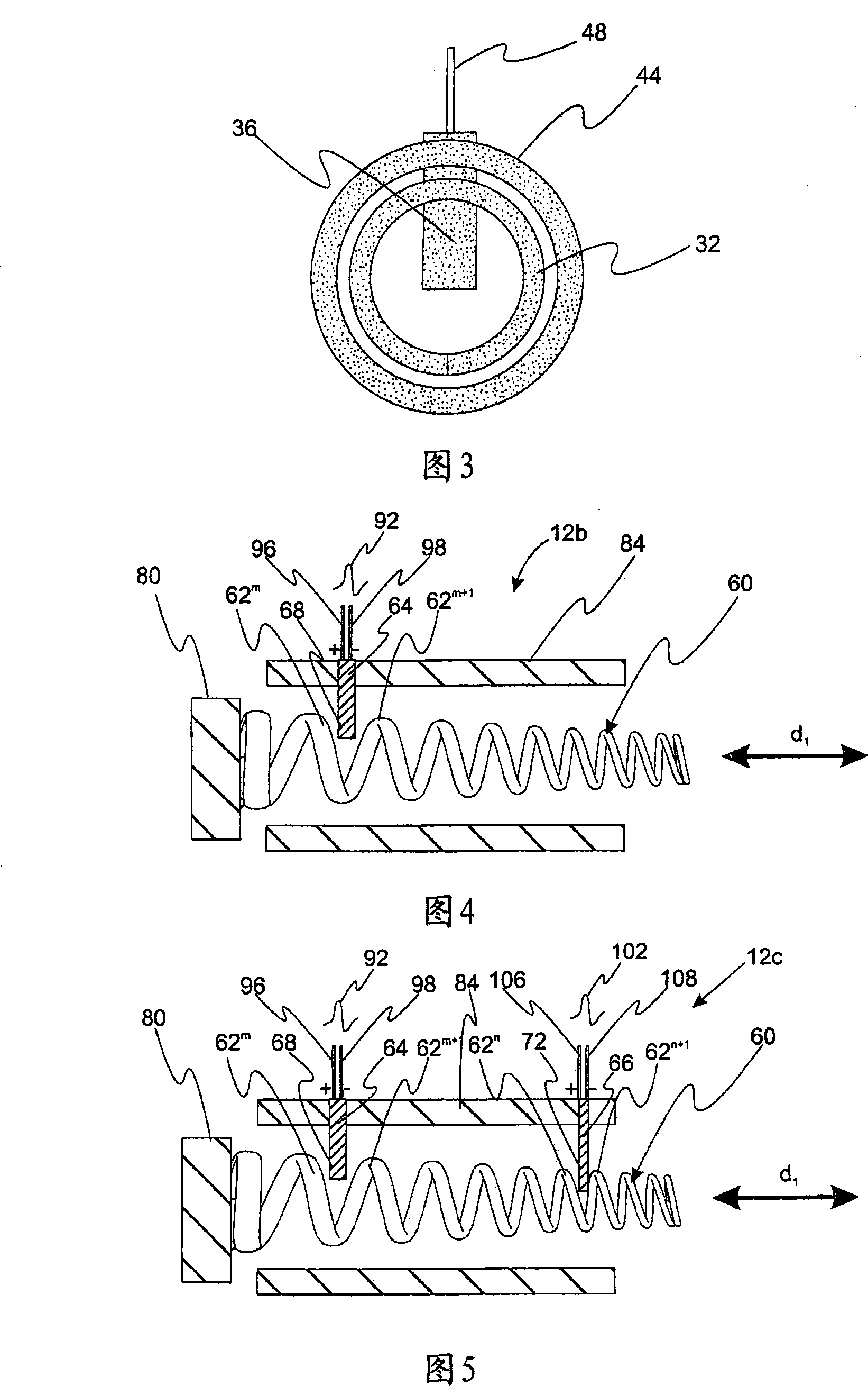
Vehicle with piezo firing spring assembly

A component and vehicle technology, applied to vehicle parts, vehicle seats, vehicle safety arrangements, etc.

Inactive Publication Date: 2008-08-20
LEAR CORP
View PDF0 Cites 4 Cited by
  • Summary
  • Abstract
  • Description
  • Claims
  • Application Information

AI Technical Summary

Problems solved by technology

While existing head restraint designs work reasonably well, improvements are needed

Method used


Image

  • Vehicle with piezo firing spring assembly
  • Vehicle with piezo firing spring assembly
  • Vehicle with piezo firing spring assembly

Examples


Embodiment Construction

[0017] Reference is now made in detail to presently preferred compositions, embodiments and methods of the invention, which form the best mode presently known to the inventors for practicing the invention. The drawings are not necessarily drawn to scale. It is to be understood, however, that the disclosed embodiments are merely exemplary of the invention, which may be embodied in different and alternative forms. Therefore, specific details disclosed herein are not to be interpreted as limiting, but merely as a representative basis for any aspect of the invention and / or as a representative basis for teaching one skilled in the art to variously employ the invention.

[0018] Except in the examples or where otherwise specifically indicated, all numerical quantities in this specification indicating materials or reaction conditions and / or quantities used are to be understood as words in describing the broadest scope of the invention "Approximately" modification.

[0019] It is al...


PUM


Abstract

An impulse detector includes a piezoelectric component and a resilient component. The resilient component has a predetermined resistance to deformation during an impact. The piezoelectric component is associated with the resilient component so that an impulse of a predetermined magnitude causes deformation of the piezoelectric component thereby generating a resulting electrical signal. An impulse responsive vehicle seat assembly incorporates the impulse detector to detect vehicle collisions.

Description

technical field [0001] The present invention relates to a piezoelectric impulse detector effective for sensor vehicle impacts. More particularly, the present invention relates to a piezoelectric shock detector incorporated into a shock responsive vehicle seat assembly. Background technique [0002] Modern vehicle designs need to comply with many government regulations. In particular, the regulations on vehicle safety requirements are complete. Regulations on a vehicle's response to a crash have been particularly successful in reducing harmful effects on vehicle occupants. The trend is for newer vehicles to meet stricter safety requirements. [0003] Recently, the regulation FMVSS 202A was adopted for the design of head restraints. The FMVSS 202A is tuned to minimize whiplash injury during low speed (10-15 km / h) rear end collisions. In such a collision, the occupant's head moves backwards and then forwards, thereby injuring the tissues within the neck. Front seats must ...

Claims


Application Information

Patent Timeline
Patent Type & Authority Applications(China)
IPC IPC(8): G01L5/00B60R21/013
CPCB60R2021/01252B60N2/4885B60R21/0136B60R2021/0048B60N2/4279B60N2/888
Inventor 约翰·F·內森
Owner LEAR CORP
Why Eureka
Try Eureka