
Double-speed recoiler

A quick-winding and winding machine technology, applied in the field of winding machines, can solve the problems of large investment in equipment, high production costs, and occupying a large amount of space in the production site.

Inactive Publication Date: 2008-08-20
朱惠兴
View PDF0 Cites 4 Cited by
  • Summary
  • Abstract
  • Description
  • Claims
  • Application Information

AI Technical Summary

Problems solved by technology

Not only does the equipment invest more, occupy more space in the production site, but also the production cost is relatively high

Method used

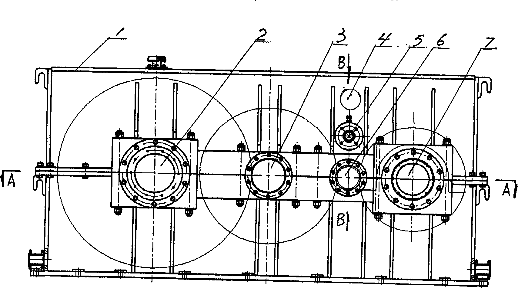
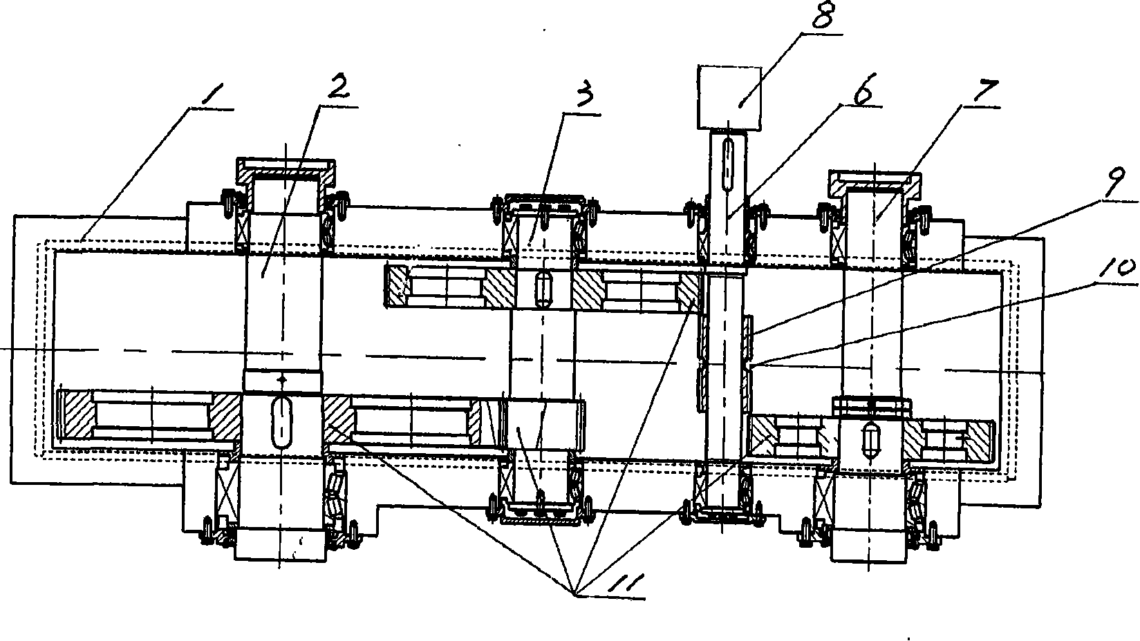
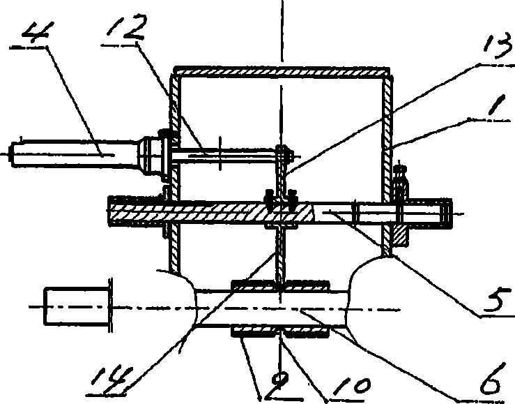

Image

  • Double-speed recoiler
  • Double-speed recoiler
  • Double-speed recoiler

Examples


Embodiment Construction

[0013] like figure 1 , figure 2 and image 3 As shown, the two-speed winder of the present invention contains a frame 1, a power shaft 6, a power mechanism 8 and a winding shaft. The frame 1 is a cuboid box-shaped structure, three shaft holes are processed on its two side walls, the three shaft holes on each side wall are at the same height, and the three shaft holes on the two side walls The holes correspond one by one. Wherein, the two ends of the power shaft 6 are rotatably installed in the middle shaft hole on the two side walls by means of bearing seats and bearings respectively. Said power mechanism 8 is arranged on the outside of the frame 1, and the power mechanism is an electric motor whose output shaft is connected with one end of the power shaft 6. The rewinding shaft includes a high-speed rewinding shaft 7 and a low-speed rewinding shaft 2, the two rewinding shafts are respectively located on both sides of the power shaft 6, and their two ends are rotatably in...


PUM


Abstract

The invention discloses a double-speed winding machine, comprising a frame, a power shaft, a power device and a winding shaft. The power shaft is connected with the power device. The power shaft is parallel with the winding shaft. The winding shaft comprises a high-speed winding shaft and a low-speed winding shaft. The two winding shafts are respectively positioned on both sides of the power shaft. A gear sleeve is arranged on the power shaft. The gear sleeve is slidingly fitted with the axial direction of the power shaft and is fixedly fitted with the circumferential direction of the power shaft. A slide bar and a cylinder are arranged above the power shaft. The cylinder is connected with the slide bar and drives the slide bar to shift vertically. A shift fork is arranged on the center of the slide bar and is connected with the gear sleeve. Gears are arranged on both the high-speed winding shaft and the low-speed winding shaft. The diameter of the gear on the high-speed winding shaft is smaller than the diameter of the gear on the low-speed winding shaft. The gear sleeve on the power shaft is respectively meshed with the gear on the high-speed winding shaft and the gear on the low-speed winding shaft under the function of the shift fork. The double-speed winding machine has the advantages of reducing the equipment investment, saving the space, lowering the production cost, and being applicable for mills rolling belt materials.

Description

technical field [0001] The invention relates to a rolling mill matching equipment. Specifically, it is the coiler on the rolling mill used to roll the strip. Background technique [0002] It is well known in the rolling mill manufacturing and application industries that after the strip is rolled, it needs to be wound on the coil head by a winder. A traditional winding machine contains a frame, a power shaft, a power mechanism and a winding shaft, and the power shaft is connected with the output shaft of the power mechanism. The power shaft is parallel to the take-up shaft, they are rotatably mounted on the frame, and are driven by gears between them. Since this winding machine has only one winding shaft, it can only install a coil head of one specification, and can only wind a rolled strip of one specification. To wind two strips of different specifications, such as two strips with a thickness of 14mm and a thickness of 0.508mm, two winding machines are required. Not onl...

Claims


Application Information

Patent Timeline
IPC IPC(8): B21C47/02
Inventor 孙大南
Owner 朱惠兴
Learn More