Eureka AIR delivers breakthrough ideas for toughest innovation challenges, trusted by R&D personnel around the world.

Valve ball control device for timing, quantitative, water-stopping self-closing water tap

A control device, faucet technology, applied in valve device, valve operation/release device, lift valve, etc., can solve problems such as lax closing of faucet, sensitivity effect, running water, etc.

Inactive Publication Date: 2008-08-06
哈尔滨兴言科技发展有限公司
View PDF1 Cites 7 Cited by
  • Summary
  • Abstract
  • Description
  • Claims
  • Application Information

AI Technical Summary

Problems solved by technology

[0003] The purpose of the present invention is to solve the problem that the control device of the existing self-closing faucet when the water is cut off is relatively complex in structure, and the sensitivity will be affected. The valve ball control device of the faucet that can be timing, quantitative, and self-closing when the water is stopped

Method used


Image

  • Valve ball control device for timing, quantitative, water-stopping self-closing water tap

Examples


specific Embodiment approach 1

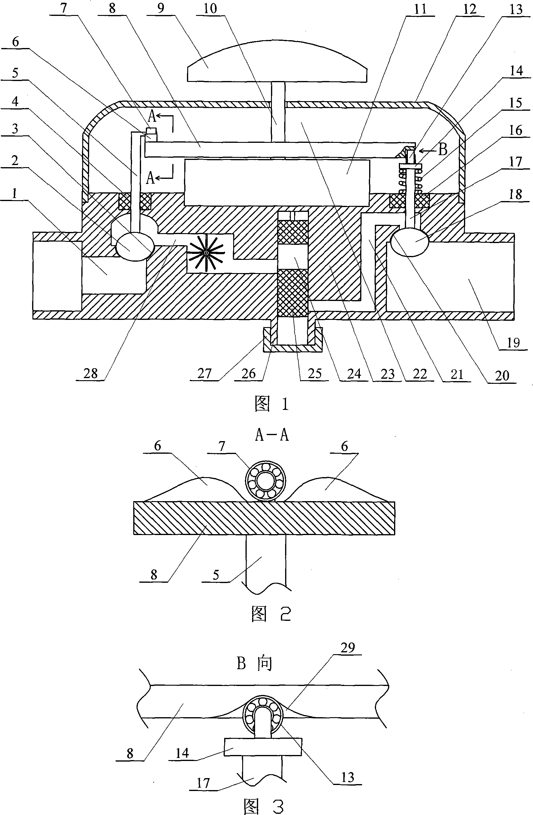
[0007] Specific embodiment one: as shown in Fig. 1, Fig. 2 and Fig. 3, this embodiment consists of a secondary valve ball 2, a secondary valve ball connecting rod 5, two bosses 6, a first bearing 7, a turntable 8, a handle 9, The timer 11, the valve cover 12, the second bearing 13, the spring support plate 14, the support spring 15, the main valve ball connecting rod 17, the main valve ball 18 and the valve body 23 are composed of the lower end of the valve cover 12 and the upper end of the valve body 23 Fixed connection, the timer 11 is fixed on the upper end of the valve body 23 in the valve cover 12, the handle 9 is arranged on the upper side of the valve cover 12, the connecting rod 10 of the handle 9 passes through the valve cover 12 and is connected with the timer 11, the valve body 23 First channel 21, buffer channel 24 and second channel 28 are arranged inside, one end of the first channel 21 communicates with the water inlet 19, the other end of the first channel 21 co...

specific Embodiment approach 2

[0008] Specific embodiment two: as shown in Figure 1, the difference between this embodiment and specific embodiment one is that it adds a first seal 4 and a second seal 16, and the first seal 4 is arranged on the secondary valve ball Between the connecting rod 5 and the valve body 23 , the second seal 16 is arranged between the main valve ball connecting rod 17 and the valve body 23 . After the first sealing member 4 and the second sealing member 16 are added, the sealing effect between the auxiliary valve ball connecting rod 5 , the main valve ball connecting rod 17 and the valve body 23 is increased. Other components and connections are the same as those in the first embodiment.

specific Embodiment approach 3

[0009] Specific embodiment three: As shown in Figure 1, the difference between this embodiment and specific embodiment two is that it increases the cleaning pipe 26 and the pipe cap 27, and the cleaning pipe 26 is fixed on the lower side of the valve body 23 and is connected with the buffer The channel 24 is connected, and the pipe cap 27 is screwed to the cleaning pipe 26 . The increased cleaning pipe 26 and pipe cap 27 form a scale chamber, which is cleaned through the cleaning pipe 26 . Other components and connections are the same as those in the second embodiment.


PUM


Abstract

A valve ball controlling device for a tap capable of timing, amount fixing and self-closing when water supply is cut off relates to a tap. The invention aims at resolving the problems that structure of control device of existing water-stopping self-closing tap is complex, sensibility is influenced, and incompletely closure of tap caused by stopped water, and water leakage after water is re-supplied. The upper portion of the main valve ball connecting rod of the invention is provided with a spring support shield, the main valve ball connecting rod between the spring support shield and the valve body is equipped with a support spring, a second bearing is arranged at the top end of the main valve ball connecting rod, the lower end of an auxiliary valve ball connecting rod is fixedly connected with upper end of an auxiliary valve ball, upper section of the auxiliary valve ball connecting rod passes through the valve body and is arranged in a cavity of a valve cover. The valve ball controlling device for a tap adapts to that the tap does not automatically close when running water stops after the tap is opened, the tap automatically stops when running water stops after the tap is opened, the water is timed and has fixed amount after the tap is opened, the tap automatically closes when time and amount are adequate and the tap automatically closes once water stops. The valve ball controlling device has the advantages of simple structure, high sensibility, and tight closure of tap when water supply is cut off.

Description

technical field [0001] The invention relates to a faucet. Background technique [0002] The patent number is ZL200420054074.5, and the name is a utility model patent of "tap water quantitative water-saving valve". The publication date is January 25, 2006, and the publication number is CN2753933. This patent can accurately and quantitatively control the water output. When the water output reaches the controlled water volume, it can be automatically closed. If the set water output is equivalent to the water receiving container, you can leave with confidence. Although water may be supplied intermittently during this period, as long as the water output reaches the desired level , to close it. But the above-mentioned tap water quantitative water-saving valve can only control the water output, and does not have the functions of self-closing and water-stopping self-closing when the time comes, and the function is relatively single. In addition, the structure of the control device...

Claims


Application Information

Patent Timeline
IPC IPC(8): F16K31/48F16K21/16F16K1/14F16K31/60
Inventor 李洪彦
Owner 哈尔滨兴言科技发展有限公司
Why Eureka
Eureka Blog
Learn More