
Flying shear for shearing corrugated plate

A technology of corrugated plates and flying shears, which is applied in the direction of knives used in shearing machine devices, devices for shearing forming blanks, shearing devices, etc., which can solve the problem that only flat plates can be cut, the end faces of corrugated plates are not vertical, and waveforms cannot be applied. Plate shearing requirements and sizing requirements, etc., to achieve the effect of easy operation, solving uneven cross-shearing sections, and high dimensional accuracy

Active Publication Date: 2012-07-04
BEIJING STAR RIVER INTEGRATED EQUIP TECH
View PDF0 Cites 0 Cited by
  • Summary
  • Abstract
  • Description
  • Claims
  • Application Information

AI Technical Summary

Problems solved by technology

[0003] In order to overcome the existing sheet and strip flying shears that can only cut flat plates and cannot be applied to the shearing requirements and sizing requirements of corrugated plates, the present invention provides a new type of flying shears, which solves the original problem by relying on its special blade form. The problem that the end surface of corrugated plate is not vertical by flying shear

Method used


Image

  • Flying shear for shearing corrugated plate
  • Flying shear for shearing corrugated plate
  • Flying shear for shearing corrugated plate

Examples


specific Embodiment approach

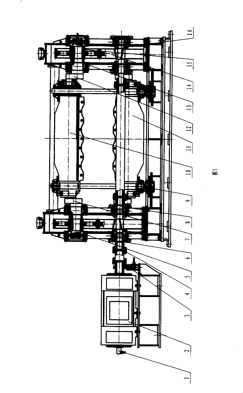
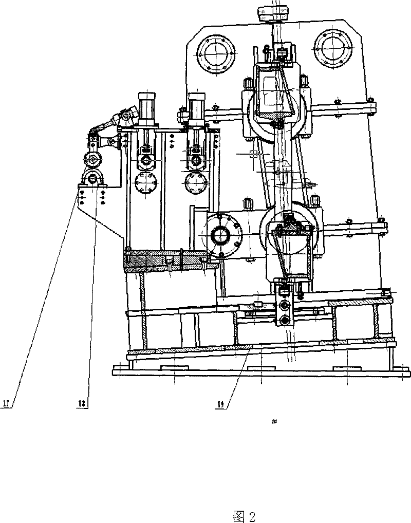
[0020] detailed description: figure 1 Including the electrical control system, the equipment consists of a servo motor 2 through a two-way coupling 4 and a left gear shaft 8 to drive the right-handed large gear 14 of the left transmission box 5 and the upper and lower left crankshaft 7 of the left-handed large gear 15. The crankshaft 7 is connected with the upper shearing device 10 and the lower shearing device 11 through bearings; the left gear shaft 8 drives the right-handed large gear 14 of the right transmission box 13 and the upper and lower right crankshaft 12 of the left-handed large gear 15 through a floating coupling , and the upper and lower right crankshafts 12 are connected with the upper shearing device 10 and the lower shearing device 11 through bearings; The guide sleeve slides up and down along the guide rod device 9, and the guide rod device 9 moves along the guide plate on the base. At the moment of shearing, the guide rod device 9 is in a vertical position. ...


PUM


Abstract

The invention provides a flying shear applicable to cutting a corrugated plate applied in metallurgy field, and includes an electric control system; the flying shear comprises an actuating motor 2, a locking device 3, a left and a right wheel boxes, an upper and a lower cutting devices, a leader device 9, a pedestal 19, a pinch roll, and a measuring motion, etc. The flying shear is characterized in that a section of the corrugated plated cut by the flying shear is vertical, whereas a section cut by a current flying shear is oblique; shapes of an upper and a lower blades are compatible with the shape of the corrugated plate; when adjusting a blade gap, the locking device is functioned as controlling a position of ''a bottom stop'' of the lower blade and a safe protection; while the pinch roll and the pinch roll of the measuring motion adopt heterotype to be suited for the waveform of the corrugated plate, thus functioned as locating a board and controlling the position of the board, and when cut, the steel plated has a fixed position; the equipment is provided with three encoders wherein the encoders are coordinated with each other according to difference of given signals, thus a controlling function of a closed loop is accomplished; a fixed length can be carried out accurately, thus ensuring that the precision of the fixed length is controlled within plus or minus 1.0mm.

Description

technical field [0001] The invention belongs to a flying shear for transverse shearing and fixed length which is suitable for a corrugated plate with a certain height and is used in the metallurgical industry. Background technique [0002] The traditional flying shears, whether it is the crankshaft pendulum flying shear or the drum flying shear, are all equipment for cutting flat plates. Since the cutting blade is linear, the horizontal component velocity of the shearing blade in the moving direction of the steel plate is equal to the workpiece speed. 1.01-1.03 times, and the movement of the shear blade is a space curve, the horizontal component and vertical component at each point of the movement track are different, applied to a corrugated plate with a certain total height, first cut the peak of the plate and then cut The spatial position of the shearing edge of the cutting wave valley is different, so the cut product is an inclined section with a certain angle, rather tha...

Claims


Application Information

Patent Timeline
Patent Type & Authority Patents(China)
IPC IPC(8): B23D25/08B23D35/00B23D33/02
Inventor 汪为健
Owner BEIJING STAR RIVER INTEGRATED EQUIP TECH
Learn More