Laser image display, and optical integrator and laser light source package used in such laser image display
一种图像显示器、光学积分器的技术,应用在光学、光学元件、图像通信等方向,能够解决寿命短、色彩再现区受限、光使用效率低等问题,达到减小斑点噪声的效果
- Summary
- Abstract
- Description
- Claims
- Application Information
AI Technical Summary
Problems solved by technology
Method used
Image

Examples
no. 1 example
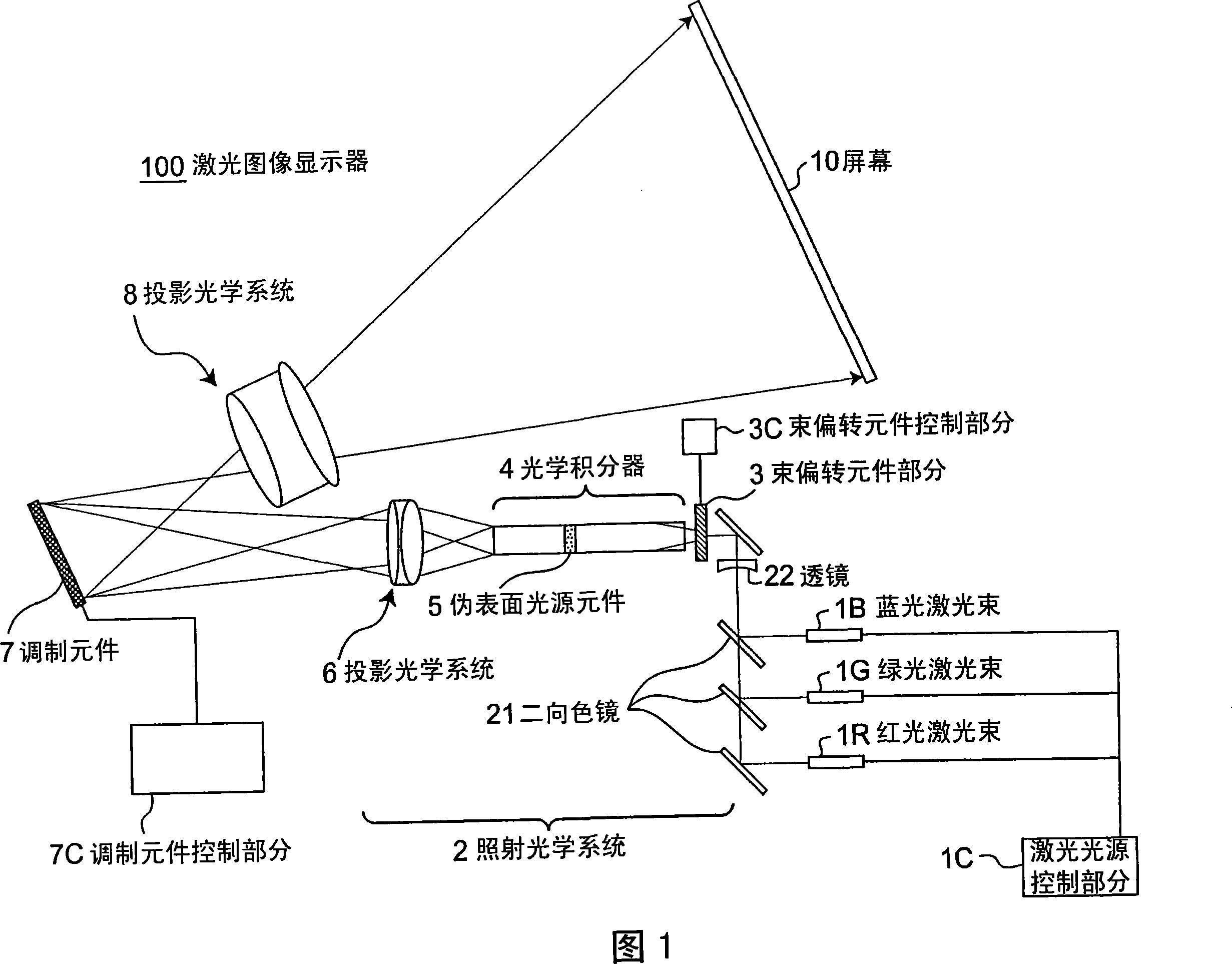
[0132] The first embodiment of the present invention is a laser image display. The laser image display is a projection display (laser display). FIG. 1 is a schematic structural diagram of a laser image display 100 according to a first embodiment of the present invention.
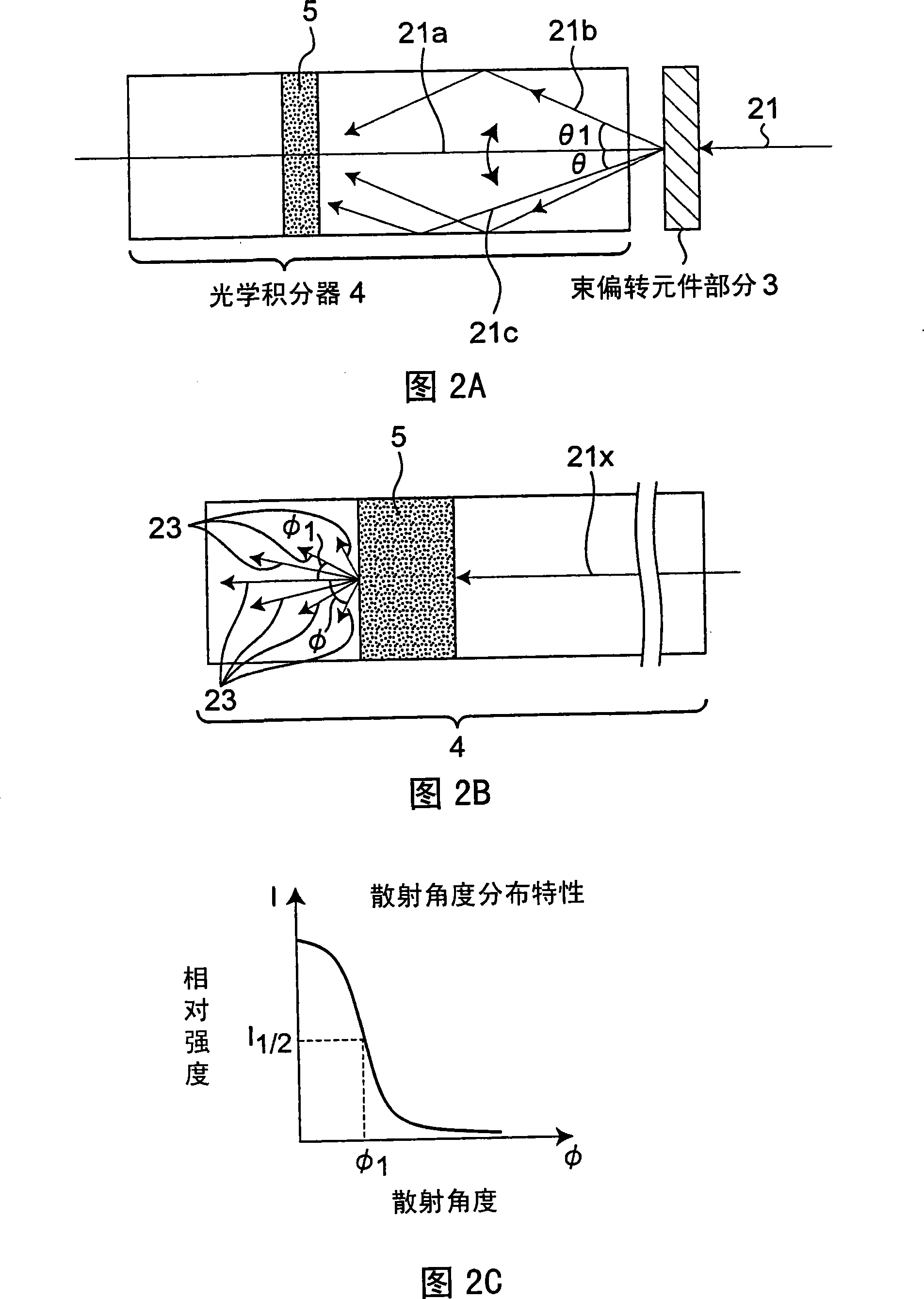
[0133] The laser image display 100 includes: laser light sources of three colors, red light (R) laser light source 1R, green light (G) laser light source 1G and blue light (B) laser light source 1B; laser light source control part 1C, executes laser light source 1R, Drive control of 1G and 1B; Dichroic mirror 21, reflecting or transmitting the laser light; Lens 22 (for example, a diverging lens); Beam deflection element part 3 deflects the advancing direction of laser light; Beam deflection element control part 3C, drives and control beam deflection element part 3; optical integrator 4, guiding the laser light; pseudo-surface light source element 5, preferably arranged inside the optical integrator 4 or arr...
example 1
[0228] FIG. 11 is a view showing a structural example of a laser light source. In FIG. 11 , the red laser light source 1R of the image display device 100 is a semiconductor laser, and the modulation element 7 has an effective surface (an area actually used for image display) in a rectangular shape. In the present invention, preferably, the longitudinal direction 1109 of the effective surface of the modulation element having a rectangular effective surface and the thickness direction 1105 of the active layer of the semiconductor laser are parallel to each other.
[0229] The active surface of the modulation element 7 has a rectangular shape corresponding to the shape of the image to be displayed, and specifically has an aspect ratio of horizontal:vertical=4:3 or 16:9. In the laser image display 100 , laser light emitted from an effective surface is expanded by a projection optical system and projected onto a screen 10 . A semiconductor laser element generally has a layered str...
example 2
[0237] The laser light sources of the laser image display 100 may be individually provided as shown in FIG. 1 , but one laser light source package may also be used. The laser light source package includes a laser light source for emitting multiple wavelengths substantially in one housing. 12 and 13 show structural examples of laser light source packages. In FIGS. 12 and 13 , illustration of the package case is omitted for clarity of the drawings.
[0238] Package example 1 shown in FIG. 12 is a laser light source package including a red semiconductor laser light source 1R, a green SHG laser light source 1Ga, and a blue semiconductor laser light source 1B. In the laser image display 100 , this package arranges each laser light source 1R or 1B so that the thickness direction 1105 of the active layer is parallel to the long-side direction 1109 ( FIG. 11 ) of the modulation element 7 . Semiconductor laser light source bases (not shown) are disposed on both sides of the semicondu...
PUM
 Abstract
Description
Claims
Application Information
 - R&D
- Intellectual Property
- Life Sciences
- Materials
- Tech Scout
- Unparalleled Data Quality
- Higher Quality Content
- 60% Fewer Hallucinations
Browse by: Latest US Patents, China's latest patents, Technical Efficacy Thesaurus, Application Domain, Technology Topic, Popular Technical Reports.
© 2025 PatSnap. All rights reserved.Legal|Privacy policy|Modern Slavery Act Transparency Statement|Sitemap|About US| Contact US: help@patsnap.com