
Motor and rotor structure thereof

A rotor structure, rotor technology, applied in the magnetic circuit shape/style/structure, magnetic circuit rotating parts, synchronous motors with static armatures and rotating magnets, etc., can solve problems such as reducing efficiency and energy loss

Active Publication Date: 2008-07-23
TECO ELECTRIC AND MACHINERY
View PDF0 Cites 15 Cited by
  • Summary
  • Abstract
  • Description
  • Claims
  • Application Information

AI Technical Summary

Problems solved by technology

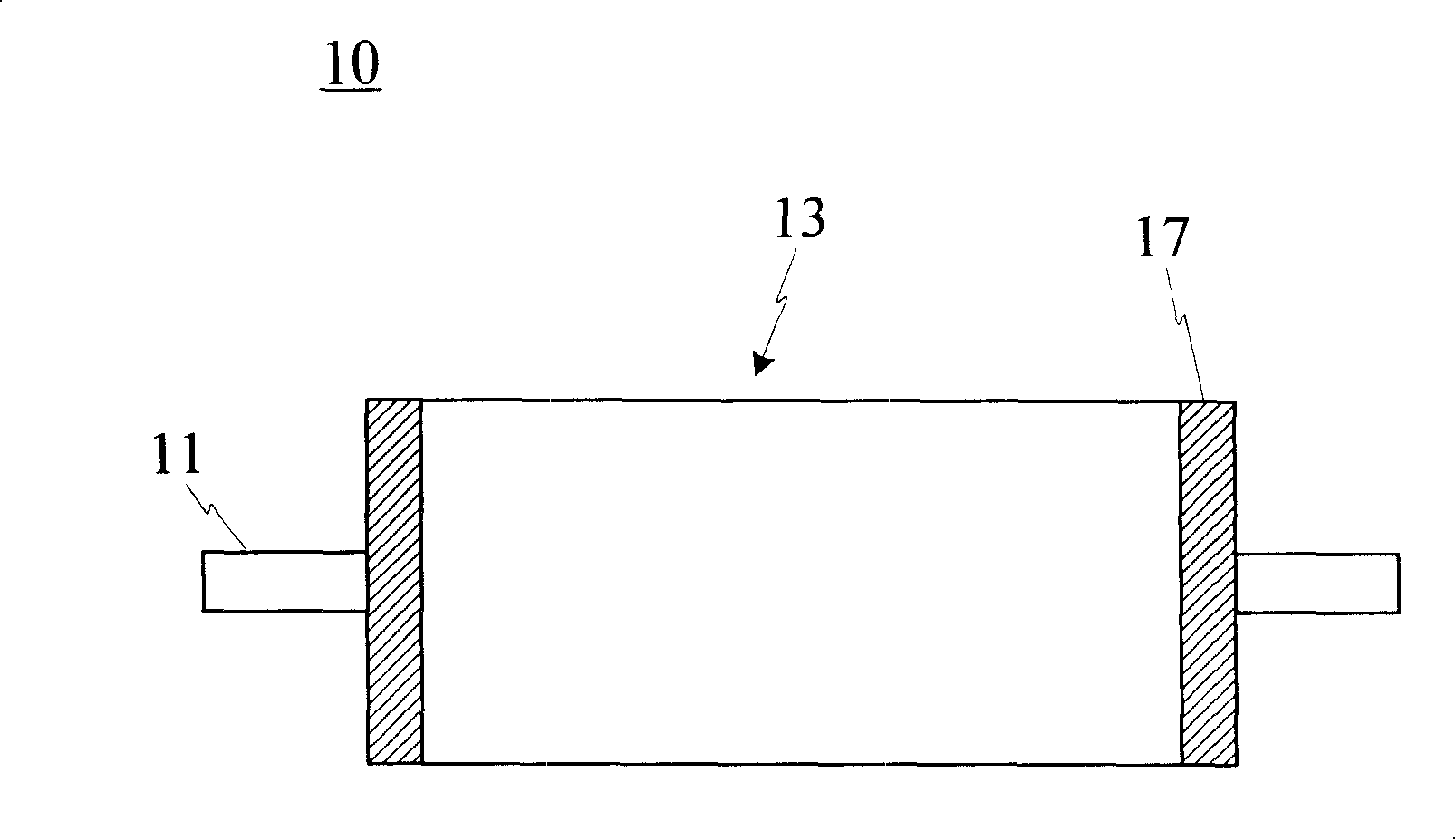
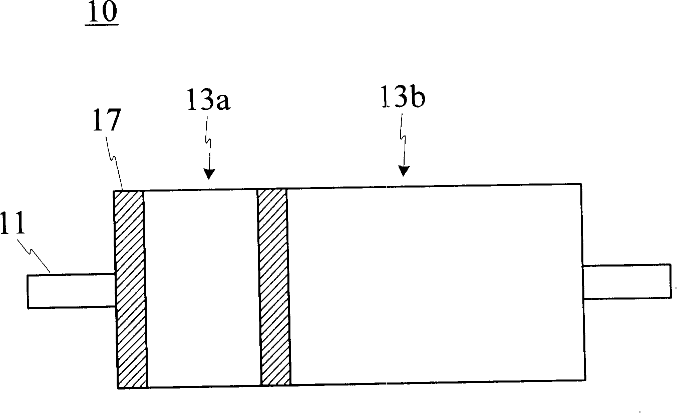
However, although this improvement can save the setting of the driver, it is supplied by the same power supply and the same group of coils with respect to the stators of the starting part 13a and the running part 13b respectively. There is no force between 13a and the stator, but there is still current passing through, resulting in energy loss and lower efficiency

Method used


Image

  • Motor and rotor structure thereof
  • Motor and rotor structure thereof
  • Motor and rotor structure thereof

Examples


Embodiment Construction

[0035] The motor disclosed in the present invention is as image 3 As shown, the cross-sectional schematic diagram of the rotor structure is shown in Figure 4 shown. The motor of the present invention mainly includes a rotor structure 30 , a stator structure 50 and a coil module 70 , wherein the rotor structure 30 has a first rotor 31 , a second rotor 33 and a rotating shaft 35 . Generally speaking, the first rotor 31 and the second rotor 33 are made of multi-silicon steel sheets stacked and riveted respectively, and the rotating shaft 35 is used to connect the first rotor 31 and the second rotor 33, and can define an axial direction, so that The first rotor 31 and the second rotor 33 can rotate on the rotating shaft 35 synchronously along the axial direction.

[0036] The stator structure 50 includes a first stator 51 and a second stator 53, respectively corresponding to the first rotor 31 and the second rotor 33, image 3 The first stator 51 and the second stator 53 show...


PUM


Abstract

A motor which can automatically start comprises a starting portion and an operating portion, wherein the starting portion is divided into a squirrel-cage type induction motor, while the operating portion is divided into a permanent type motor, the starting portion and the operating portion are separately arranged along the same axis, and wire windings thereof are respectively connected with a alternating-current power supply, the wire winding on the starting portion can be provided with a switch, when the starting portion drives the motor to achieve a synchronous speed, the operating portion is used to keep a synchronous operation of the motor and can close the starting portion to reduce copper loss.

Description

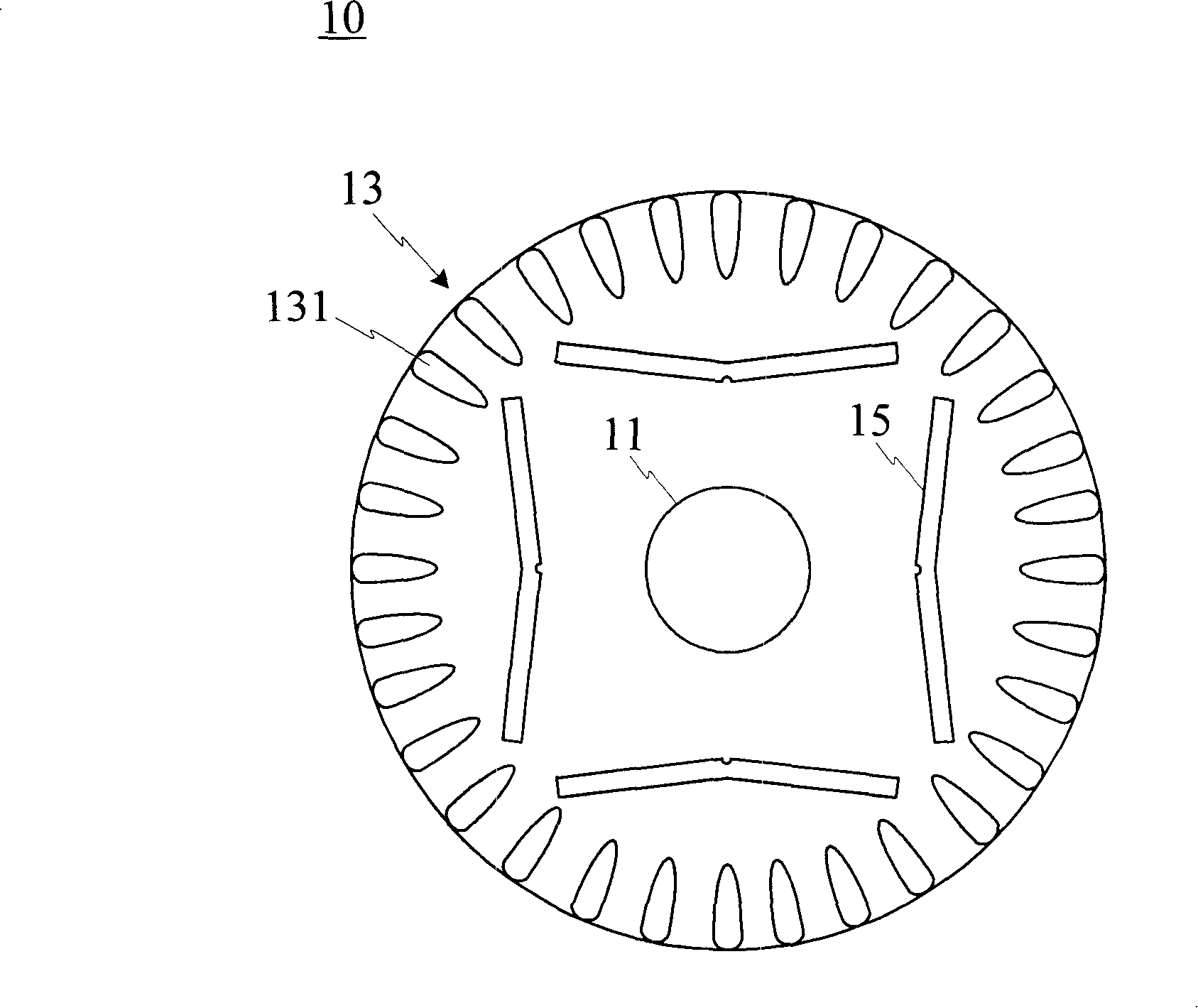
technical field [0001] The invention relates to a motor and its rotor structure; in particular, it relates to a motor whose rotor has a starting part and a running part. Background technique [0002] Today’s daily operations in many industries often rely on power to drive machinery to rotate or other forms of movement. At this time, motors are usually selected as the power source; because motors can convert electrical energy or magnetic energy into mechanical energy, they are widely used in It has become an indispensable equipment in various industries, electrical appliances, transportation systems and other devices. There are several types of motors, such as induction motors, permanent magnet motors, etc. Different types of motors can be selected according to different environments and conditions. [0003] Among them, the self-starting permanent magnet synchronous motor has its advantages. It has the design of the starting part and the running part through the rotor struct...

Claims


Application Information

Patent Timeline
IPC IPC(8): H02K16/00H02K21/46H02K1/27H02K17/16H02K21/12
CPCH02K21/12H02K7/20H02K16/00H02K17/20
Inventor 洪联馨陈明祥
Owner TECO ELECTRIC AND MACHINERY
Learn More