
Windmill and wind power generator composed of the same

A wind power generation device and windmill technology, which is applied to wind turbines, wind energy power generation, wind turbines and other directions that are consistent with the wind direction, and can solve problems such as the influence of generators and the uneven rotation speed of windmills.

Active Publication Date: 2008-07-23
蓝星环保能源有限公司
View PDF0 Cites 7 Cited by
  • Summary
  • Abstract
  • Description
  • Claims
  • Application Information

AI Technical Summary

Problems solved by technology

The disadvantage of this fixed-inclination blade is that when the wind blows from the rear, the torque on the windmill is opposite to the direction in which the windmill rotates against the wind. If the upper side is tilted backward, the windmill will turn clockwise when the wind blows from front to back; if the tilt angle is reversed, the steering will also be reversed, but at the same tilt angle, if the wind blows from back to front, the windmill will turn counterclockwise. When the windmill is clockwise
In addition, due to the uneven wind speed caused by the wind force, the generator will be affected to a certain extent.

Method used


Image

  • Windmill and wind power generator composed of the same
  • Windmill and wind power generator composed of the same
  • Windmill and wind power generator composed of the same

Examples


Embodiment Construction

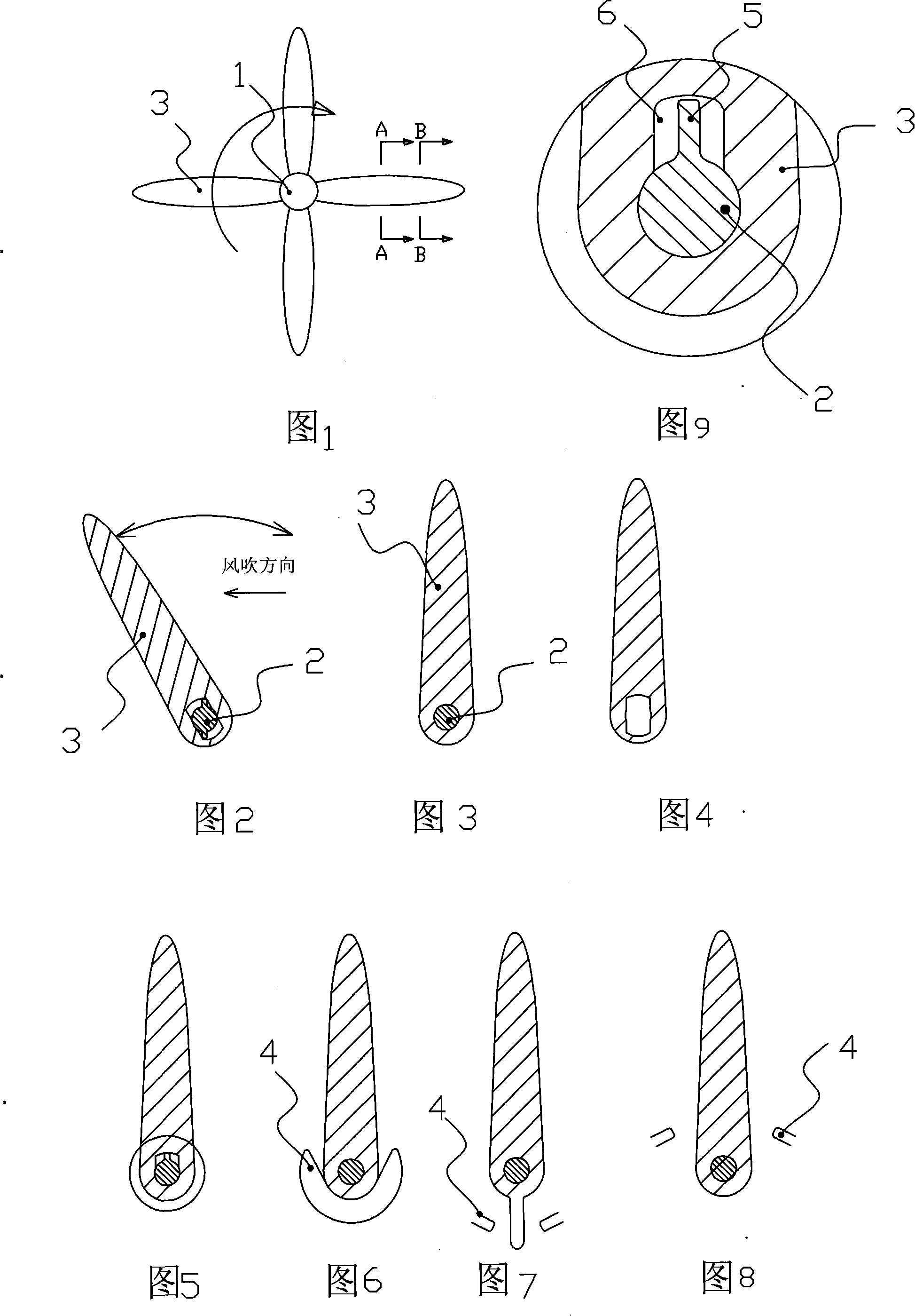
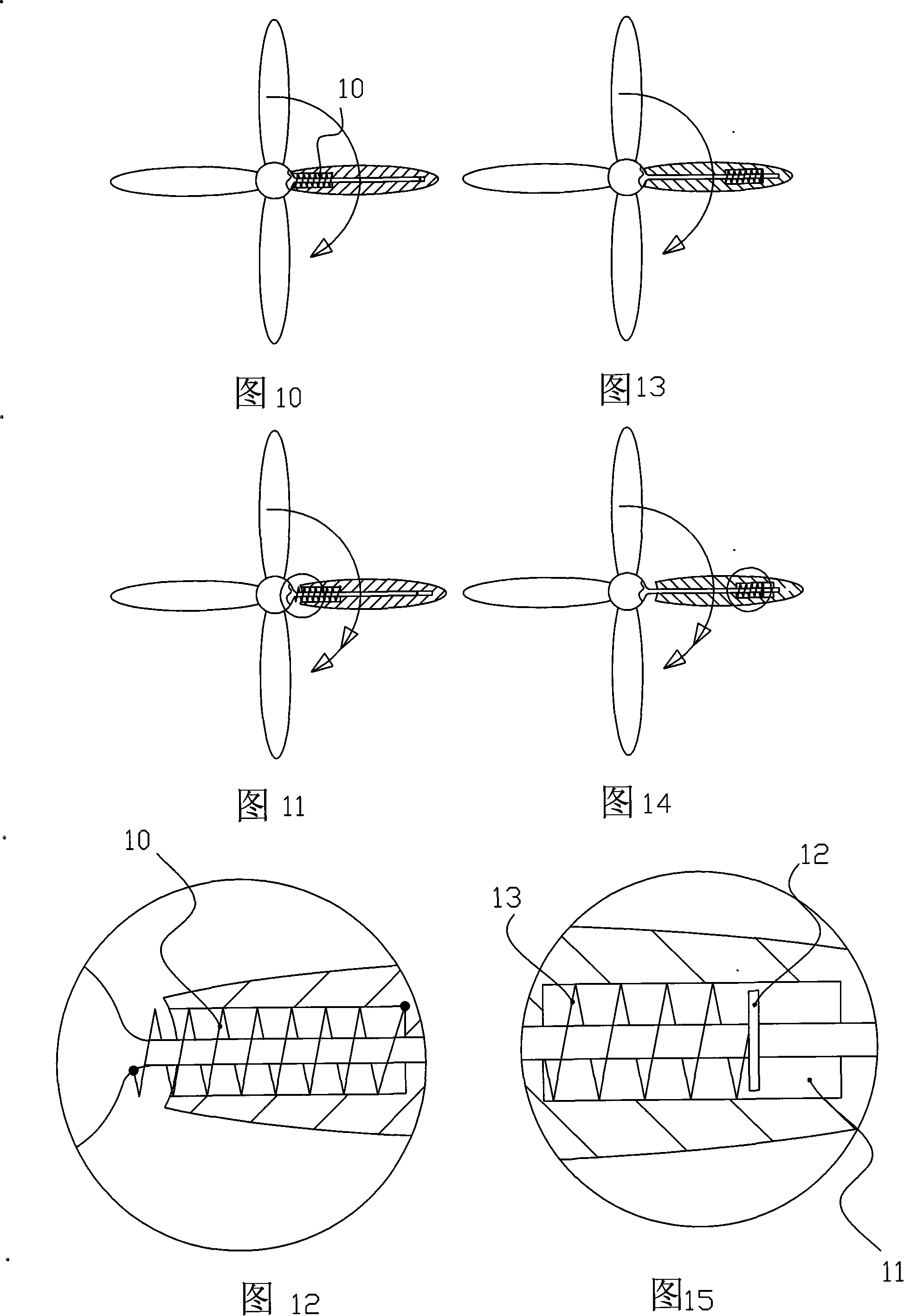
[0043] As shown in Figures 1 to 4, the windmill embodiment 1 of the present invention includes a wind wheel composed of a horizontal shaft 1 and blades 3, the blades are swingably supported on a blade shaft 2 vertically fixed on the horizontal shaft 1, The axis of the blade shaft is parallel to the length direction of the windmill blade and is biased to the blade edge on one side of the blade. The horizontal shaft or the blade shaft is provided with a blade swing limit mechanism. The swing limit mechanism in this example is: the blade shaft passes through the blade shaft hole Among them, there is at least one radial protrusion on the blade shaft, and a radial groove is opened at the blade shaft hole corresponding to the radial protrusion, see Figure 2, which is a schematic diagram taken along the A-A line of Figure 1, the present example The radial protrusion is protruding at both ends, and the blade shaft hole corresponding to the radial protrusion has a radial groove 6, so th...


PUM


Abstract

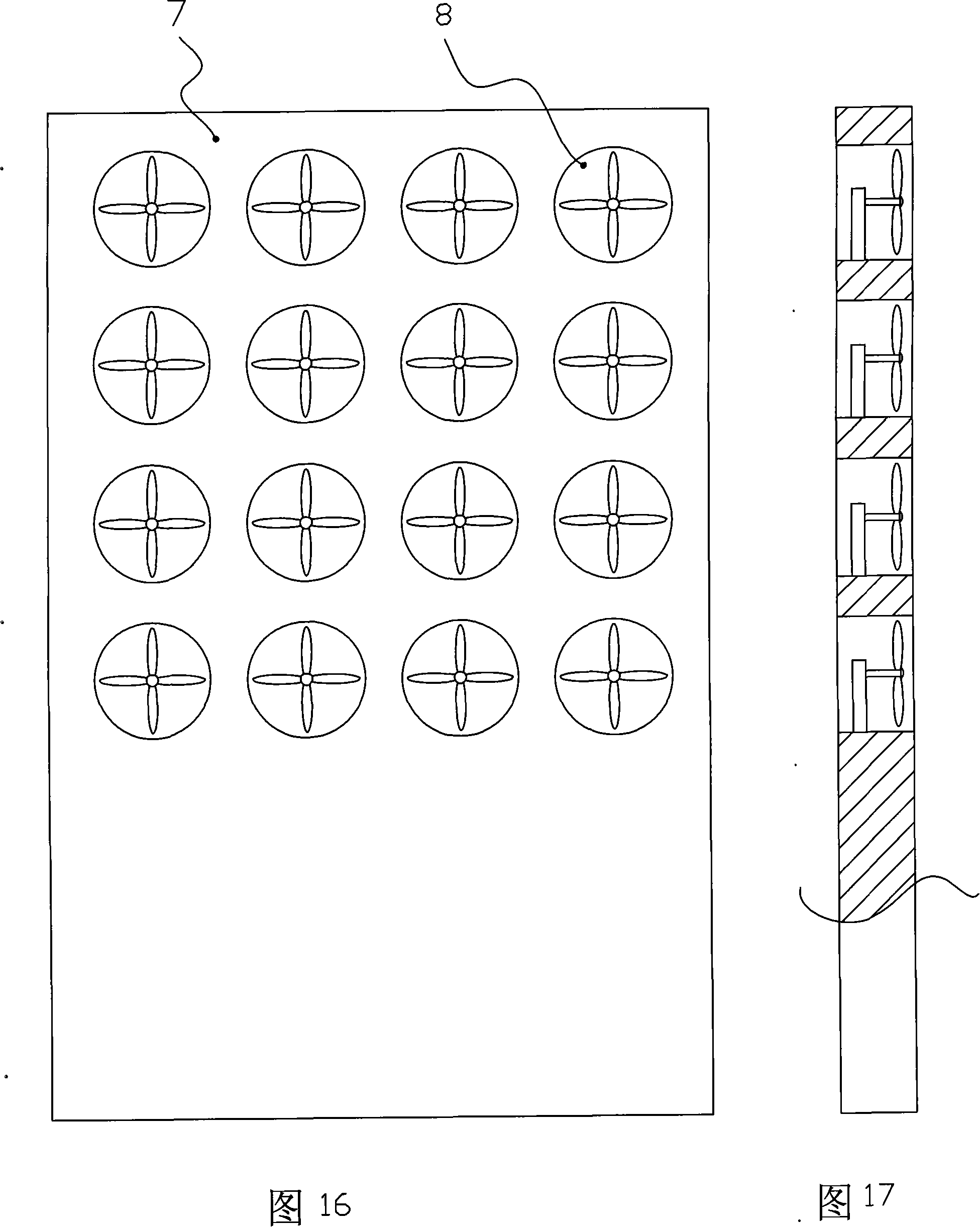
The invention relates to a windmill, comprising a wind wheel which is formed from a horizontal rotating shaft (1) and vanes (3). The vane is swingly borne on a vane shaft (2) which is vertically fixed on the horizontal rotating shaft. The vane shaft leans to a side of the vane. A vane swinging limit apparatus is arranged on the horizontal rotating shaft or on the vane shaft. The vane shaft is perforated in the vane shaft hole. A radial convex (5) is arranged on the vane shaft. A radial groove (6) or a limit block (4) is arranged on the corresponding vane shaft hole. The limit block (4) is fixed on the horizontal rotating shaft or on the vane shaft and protrudes into both sides of the vane. The vane and the vane shaft are slidingly matched and connected with each other through an extension spring (10). The vane can automatically swing to proper obliquity according to wind from the front or from the back, so that the windmill bears homodromous torque whether the wind blows to the vane from the front or from the back. In the wind power generation device comprising the windmill, a plurality of windmills are arranged the corresponding numbers of horizontal air holes (8) on a vertical wall (7). The vertical wall integrates the wind power, increases the wind power passing the wind tunnel, and improves the power generation capability of the windmill.

Description

technical field [0001] The invention relates to a windmill and a wind power generating device composed of the windmill. Background technique [0002] A windmill, also called a wind turbine, is a power machine that uses wind as energy without fuel. Wind turbines are mainly composed of wind energy receiving devices, control mechanisms, transmissions, supports, etc. Conventional wind turbines with wind rotors as wind energy receiving devices can be divided into two types: horizontal axis structure and vertical axis structure. The wind wheel is mainly composed of a rotating shaft and a blade group. The blades of the existing horizontal rotating shaft wind wheel are mostly directly fixed on the horizontal rotating shaft. The blades are not in the same plane, but slightly inclined to the vertical plane, with a fixed inclination angle. In this way, the windmill can only rotate against the wind, and the direction of inclination determines the direction of rotation of the windmill w...

Claims


Application Information

Patent Timeline
Patent Type & Authority Applications(China)
IPC IPC(8): F03D1/06F03D1/04F03D9/00F03D9/34
CPCY02E10/721Y02E10/72
Inventor 陈克敏
Owner 蓝星环保能源有限公司
Learn More