Eureka AIR delivers breakthrough ideas for toughest innovation challenges, trusted by R&D personnel around the world.

Cooling rib direct driven permanent magnetic synchronous single bearing aerogenerator

A wind turbine and permanent magnet synchronous technology, applied to synchronous motors with stationary armatures and rotating magnets, electrical components, electromechanical devices, etc., can solve the inconvenience of transportation and hoisting, low motor performance indicators, and unpredictable temperature rise and other problems, to achieve the effect of compact structure, good protection effect, increased reliability and service life

Inactive Publication Date: 2008-07-16
XIANGTAN ELECTRIC MFG CORP LTD
View PDF0 Cites 17 Cited by
  • Summary
  • Abstract
  • Description
  • Claims
  • Application Information

AI Technical Summary

Problems solved by technology

[0002] The direct-drive permanent magnet generators developed by various motor manufacturers at home and abroad, after actual operation, although some have been connected to the grid for power generation, the operation is still unstable, and the reliability needs to be further verified and improved. There are still a lot of problems in heat dissipation analysis, support structure, etc., which make the performance index of the motor low, the temperature rise unpredictable, the control characteristics are not good, and the motor is too heavy, which is very inconvenient for transportation and hoisting, and it is very easy to cause mechanical deformation during the hoisting process
For example, the 1.2MW direct-drive permanent magnet generator produced by Vensys in Germany and imported by a company in my country adopts the structure of outer rotor and inner stator. Although the operating efficiency is high, its own heat dissipation capacity is very poor, and internal auxiliary ventilation is required. heat dissipation in order to function properly

Method used


Image

  • Cooling rib direct driven permanent magnetic synchronous single bearing aerogenerator

Examples


Embodiment Construction

[0007] The present invention will be described in further detail below in conjunction with the accompanying drawings and embodiments.

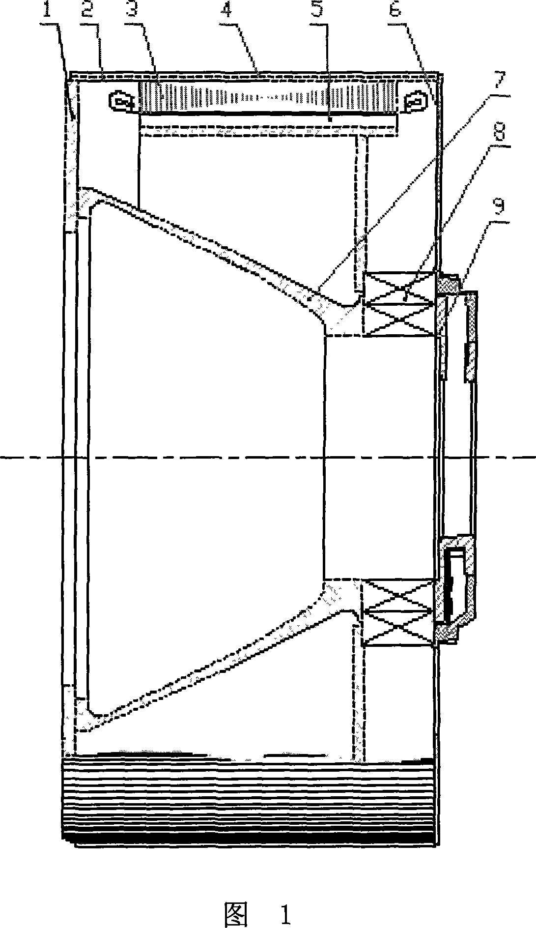
[0008] Referring to the accompanying drawings, this embodiment includes an end plate 1, a frame 2, a stator 3, a rotor 5, and an end cover 6. 5 is composed of two concentric cylinders, and windings and permanent magnets are respectively provided on their two opposite surfaces. The stator 3 is fixed in the frame 2, and the rotor 5 rotating relative to the stator 3 is fastened to the outer ring of the bearing 8 Above, the inner ring of the bearing 8 is connected to the conical support 7, the conical support 7 is connected to the end plate 1, and the side of the bearing 8 located on the hub side of the fan is connected to a brake 9.

[0009] Before the present invention is connected with the nacelle and the fan hub, it can be assembled separately into a whole. First, the stator 3 and the base 2 are assembled into one body, and the conical suppor...


PUM


Abstract

The invention provides a radiating rib direct driving permanent magnet synchronous single bearing anemo-electric generator, comprising an end sheet (1), a frame (2), a stator (3), a rotor (5) and an end closure (6), wherein, the frame (2) is connected with the end sheet (1), the stator (3) is fixed inside the frame (2). The invention is characterized in that the outside circumference of the frame (2) is provided with a radiating rib (4), both the stator (3) and the rotor (5) consist of two concentric cylinders, the two corresponding surfaces are respectively provided with a winding and a permanent magnet, the rotor (5) which rotates corresponding to the stator (3) is closely fixed on the outer lane of a bearing (8), the inner lane of the bearing (8) is connected with a taper support (7) which is connected with the end sheet (1), the lateral surface of the bearing (8) positioned on the blower hub side is connected with an arrester (9). The invention has simple and compact structure, good radiating effect, high efficiency and convenient transportation and installation.

Description

technical field [0001] The invention relates to a permanent-magnet synchronous wind-driven generator, in particular to a heat-dissipating rib direct-drive permanent-magnet synchronous single-bearing wind-driven generator. Background technique [0002] The direct-drive permanent magnet generators developed by various motor manufacturers at home and abroad, after actual operation, although some have been connected to the grid for power generation, the operation is still unstable, and the reliability needs to be further verified and improved. There are still a lot of problems in heat dissipation analysis, support structure, etc., which make the performance index of the motor low, the temperature rise unpredictable, the control characteristics are not good, and the motor is too heavy, which is very inconvenient for transportation and hoisting, and it is very easy to cause mechanical deformation during the hoisting process . For example, the 1.2MW dir...

Claims


Application Information

Patent Timeline
IPC IPC(8): H02K5/18H02K7/18H02K7/10H02K21/12
Inventor 李春林杨国伟王步瑶刘智勇扬小林杨振河
Owner XIANGTAN ELECTRIC MFG CORP LTD
Why Eureka
Eureka Blog
Learn More