Tool bit effective machining area calculation based on three scan line and cutter path creation method

A tool path and processing area technology, which is applied in the field of effective processing area calculation and tool path generation based on three-scanning lines, can solve the problem that the tool path is not well resolved, and achieve the effect of improving calculation efficiency

Inactive Publication Date: 2011-06-01
XI AN JIAOTONG UNIV
View PDF0 Cites 0 Cited by
  • Summary
  • Abstract
  • Description
  • Claims
  • Application Information

AI Technical Summary

Problems solved by technology

However, the use of MasterCAM software to generate tool paths requires extensive expertise such as tool path parameters, especially the optimization of tool paths has not been well resolved

Method used


Image

  • Tool bit effective machining area calculation based on three scan line and cutter path creation method
  • Tool bit effective machining area calculation based on three scan line and cutter path creation method
  • Tool bit effective machining area calculation based on three scan line and cutter path creation method

Examples


Embodiment Construction

[0025] The present invention will be further described in detail below in conjunction with the accompanying drawings.

[0026] Figure 1 is a flowchart of the optimal tool path generation based on the three-scanning line method. Referring to the flowchart, the process of generating the optimal tool path is described as follows:

[0027] Step 1, determine polygon, scanning direction, step distance (feed amount).

[0028] In step 2, each vertex of the polygon is transformed into a new coordinate system with the scanning line direction as the x-axis.

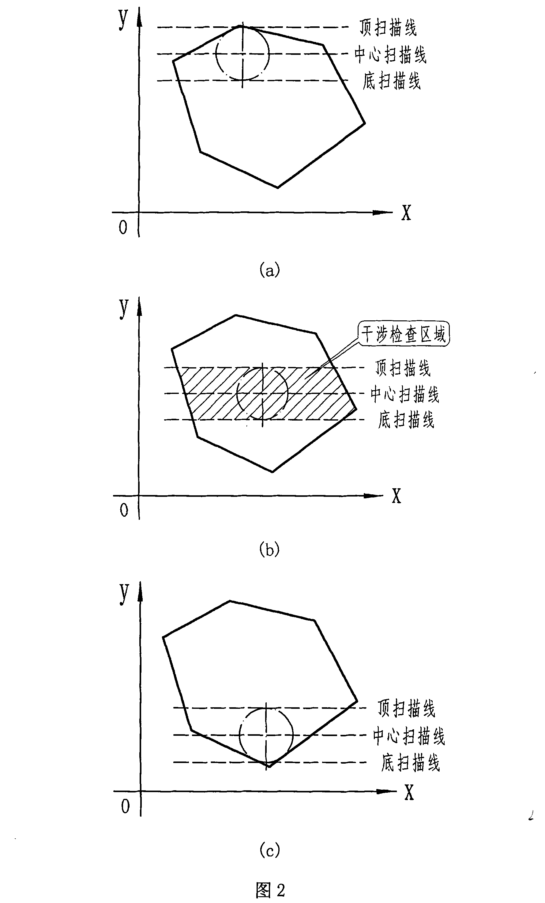
[0029] Step 3, align the bottom scan line of the scan line with the lowest point (line) of the polygon.

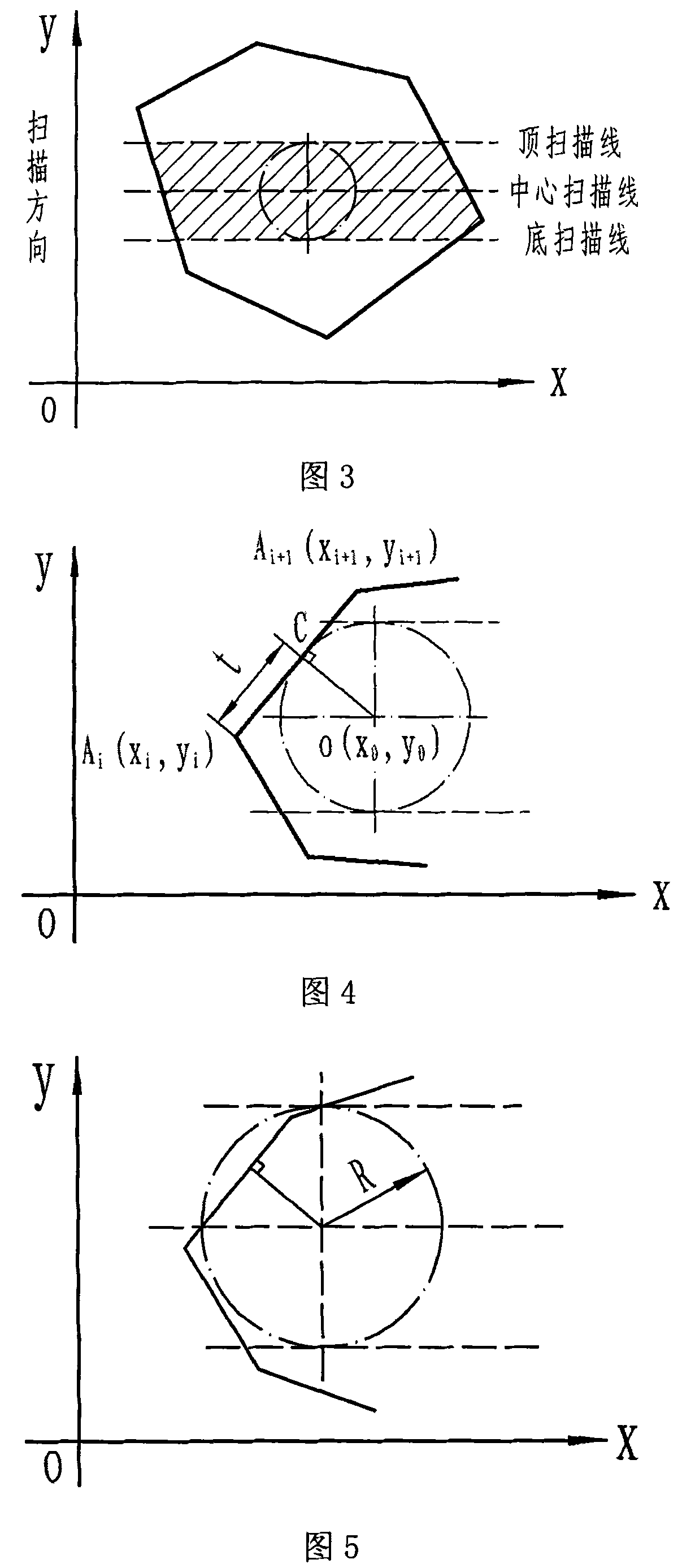
[0030] Step 4, each double scan line (top scan line and bottom scan line) executes step 5 to step 9 loop operation until there is a reasonable tool path.

[0031] Step 5, calculate the intersection point of the two straight lines and the polygon, use the topological relationship to determine the corresponding edge sets, and th...


PUM


Abstract

The invention discloses a method of calculating an effective processing area of a cutter and generating a cutter path based on three scanning beams. The method provides a model of the three scanning beams, and determines an effective scope of a central cutter path based on three-scanning-beam scanning principles and in combination with specific cutter parameters, thereby simplifying interference detection and calculation of the cutter path; meanwhile, since the effective processing area of the cutter describes an actual cutting area of the cutter in the processing process, which is the key basis for calculating the cutter path and the cutter abrasion cost, the invention puts forward a method for calculating the effective processing area of the cutter based on the scanning-beam algorithm in virtue of the thoughts of a scanning-beam filling method; an initial cutting feed position and an off working-piece position of the cutter are determined through the two up and down scanning beams, thereby effectively controlling a searching scope of the interference detection of the cutter and the working piece and greatly improving the calculation efficiency; an optimized cutter path is generated through the interference detection method and the calculation principles of non-interference cutter paths of the cutter and the working piece.

Description

technical field [0001] The invention relates to a CNC machine tool processing method for processing parts in the field of mechanical manufacturing, in particular to a method for calculating the effective processing area of ​​a tool based on three scanning lines and generating a tool track. The method uses the processing plan evaluation and tool track during multi-tool combined processing generation. Background technique [0002] With the rapid development of modern numerical control technology, numerical control machining has become the main processing form in the machinery manufacturing industry. In the modern manufacturing environment, it is becoming more and more important to formulate the purpose and specification of tool selection. In the traditional manufacturing process, the choice of cutting tools is often chosen by the machine tool operator, whose technical level plays a decisive role in the selection of cutting tools in each processing procedure and the machining a...

Claims


Application Information

Patent Timeline
Patent Type & Authority Patents(China)
IPC IPC(8): G05B19/19
Inventor 张英杰高建民陈富民李云龙张瑜
Owner XI AN JIAOTONG UNIV
Why Eureka
Try Eureka