
Side light type backlight module group

A backlight module, side-light technology, applied in the field of side-light backlight modules, can solve the problem of narrow color gamut of cold cathode lamps, achieve good flexibility, increase the color gamut range, and improve the use efficiency

Inactive Publication Date: 2008-07-09
上海广电光电子有限公司
View PDF0 Cites 9 Cited by
  • Summary
  • Abstract
  • Description
  • Claims
  • Application Information

AI Technical Summary

Problems solved by technology

However, cold cathode lamps have disadvantages such as narrow color gamut and the need to use mercury as raw material for production.

Method used


Image

  • Side light type backlight module group
  • Side light type backlight module group

Examples


Embodiment Construction

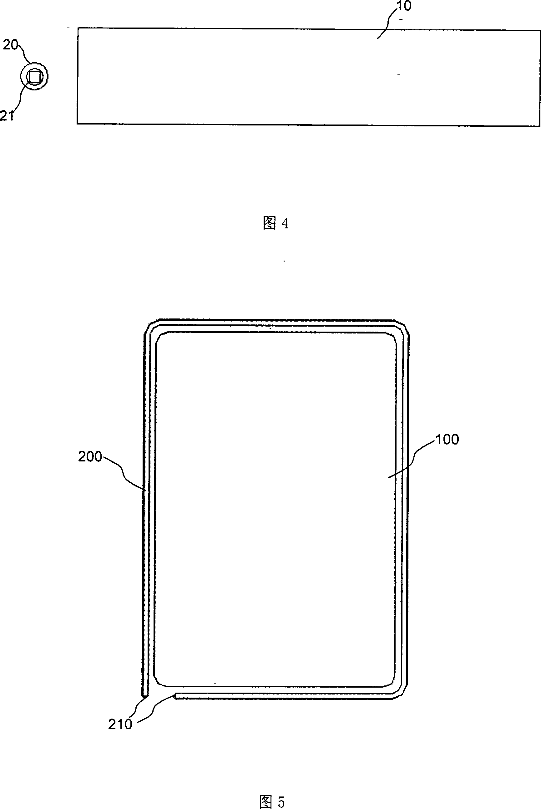
[0013] Embodiments of the present invention will be further described below in conjunction with accompanying drawings:

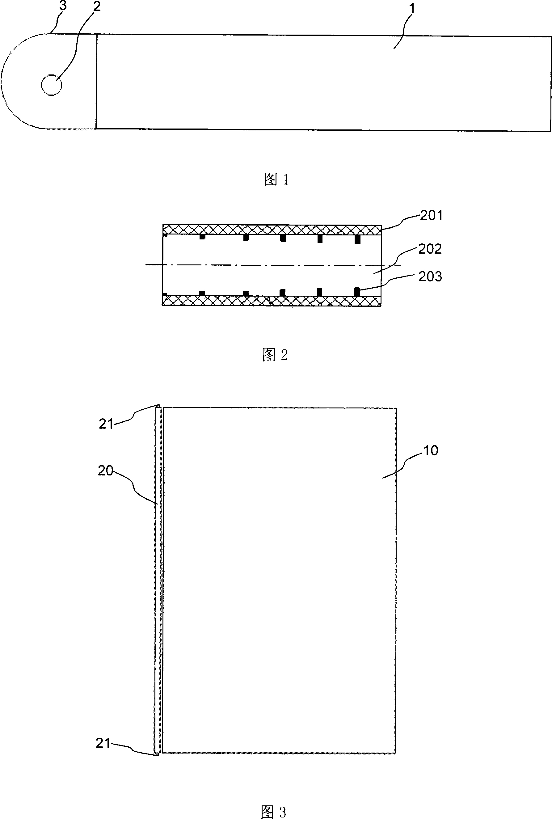
[0014] Fig. 2 is a schematic structural view of a whole-body light-emitting fiber, which is also called a side-light-emitting fiber or an illuminating fiber. Produced by the current known optical fiber technology, the whole-body light-emitting optical fiber is composed of a cladding 201, a core 202, and a scatterer 203. The cladding 201 is coated on the outer surface of the core 202, and the scatterer 203 is distributed on the core with a certain density and depth. The inner surface of the layer 22, wherein the refractive index of the cladding layer 201 is greater than the refractive index of the core layer 202, and the scatterer 203 is made of a material different from the refractive index of the core layer 202, and the cladding layer 201 and the core layer 202 constitute a circular waveguide structure. The guided light propagates in the core layer 02, and...


PUM


Abstract

The invention discloses a side-edge backlight module of an LCD. The side-edge backlight module comprises a light guide plate, a surface light-emitting optical fiber arranged on the side edge of the light guide plate; and light sources respectively arranged on both ends of the surface light-emitting optical fiber. The side-edge backlight module of the invention has the advantages of improved light utilization efficiency, improved color gamut range, thinned product, etc.

Description

technical field [0001] The invention relates to a side-light backlight module of a liquid crystal display, in particular to a side-light backlight module using a whole-body light-emitting optical fiber to provide a light source. Background technique [0002] Liquid crystal display (LCD) uses the change of the electric field strength clamped on the liquid crystal molecules to change the orientation of the liquid crystal molecules to control the intensity of light transmission to display images. Generally speaking, a complete liquid crystal display must have a backlight module, a polarizer, a TFT (thin film transistor) lower substrate, a CF (color filter) upper substrate, and a liquid crystal molecule layer filled in a box composed of two substrates. The liquid crystal substrate itself cannot emit light and needs a light source. At present, most liquid crystal displays use cold-cathode lamps as light sources. Figure 1 is a schematic diagram of an existing side-light backlight...

Claims


Application Information

Patent Timeline
Patent Type & Authority Applications(China)
IPC IPC(8): G02F1/13357F21V8/00G02F1/1335
Inventor 李郑阳
Owner 上海广电光电子有限公司
Learn More