Electric filter light modulation apparatus

A dimming device and filter technology, applied in installation, optics, optical components, etc., can solve the problems of impossible and inconvenient dimming, and achieve the effects of easy control, low noise, and improved dimming efficiency

Inactive Publication Date: 2008-07-09
INST OF OPTICS & ELECTRONICS - CHINESE ACAD OF SCI
View PDF0 Cites 5 Cited by
  • Summary
  • Abstract
  • Description
  • Claims
  • Application Information

AI Technical Summary

Problems solved by technology

However, since modern optical instruments are already a combination of optics, electromechanics, and the requirements for the dimming method of optoelectronic instruments have developed from a single manual to an intelligent electric direction; way of dimming is not only inconvenient but also impossible

Method used


Image

  • Electric filter light modulation apparatus
  • Electric filter light modulation apparatus
  • Electric filter light modulation apparatus

Examples


Embodiment Construction

[0017] The present invention will be described in detail below in conjunction with the accompanying drawings and specific embodiments.

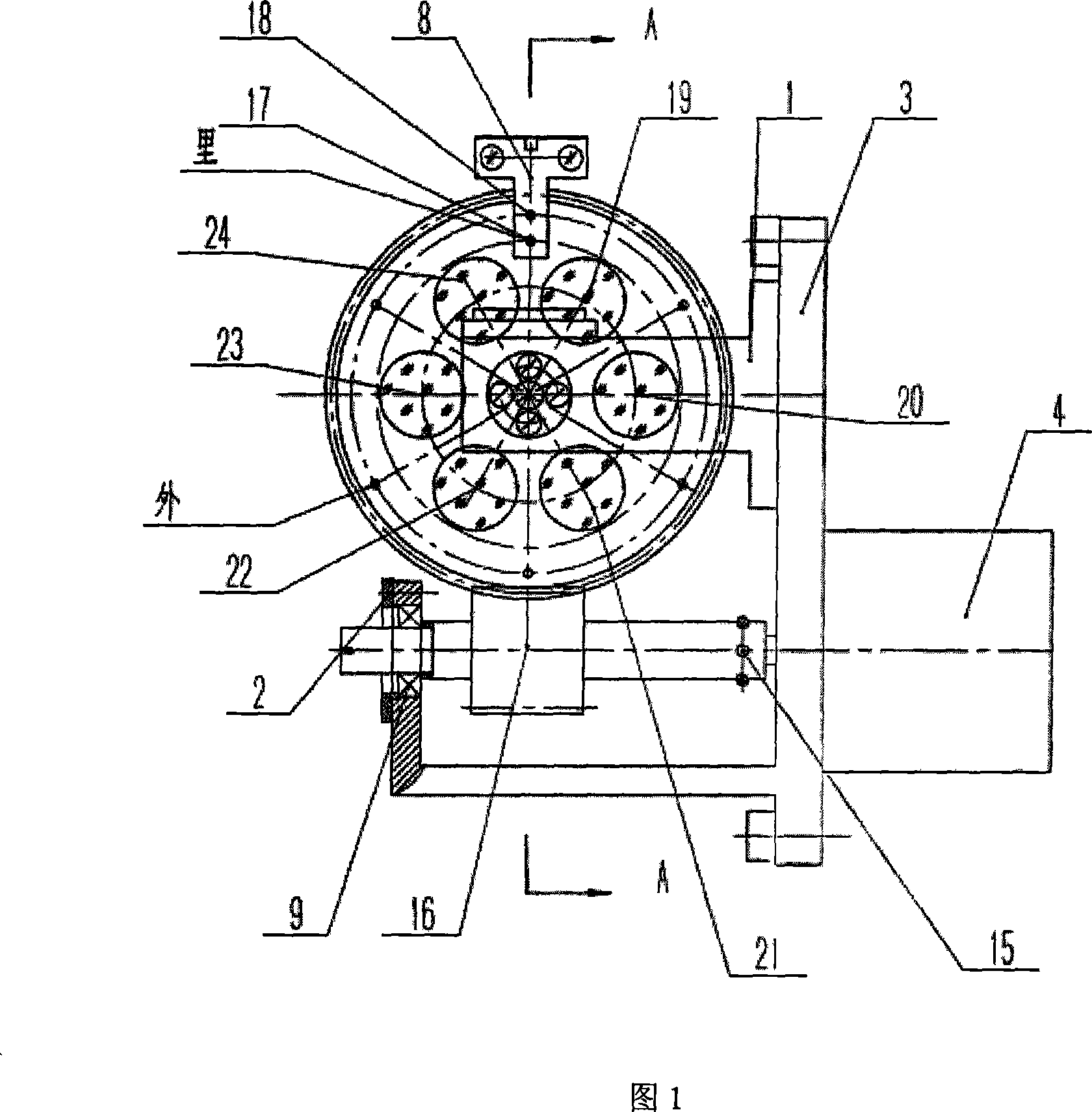
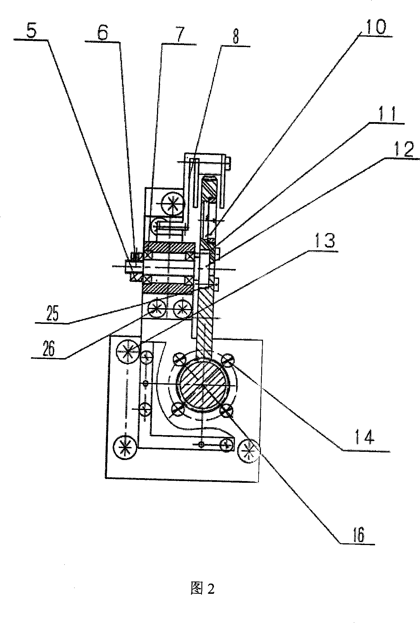
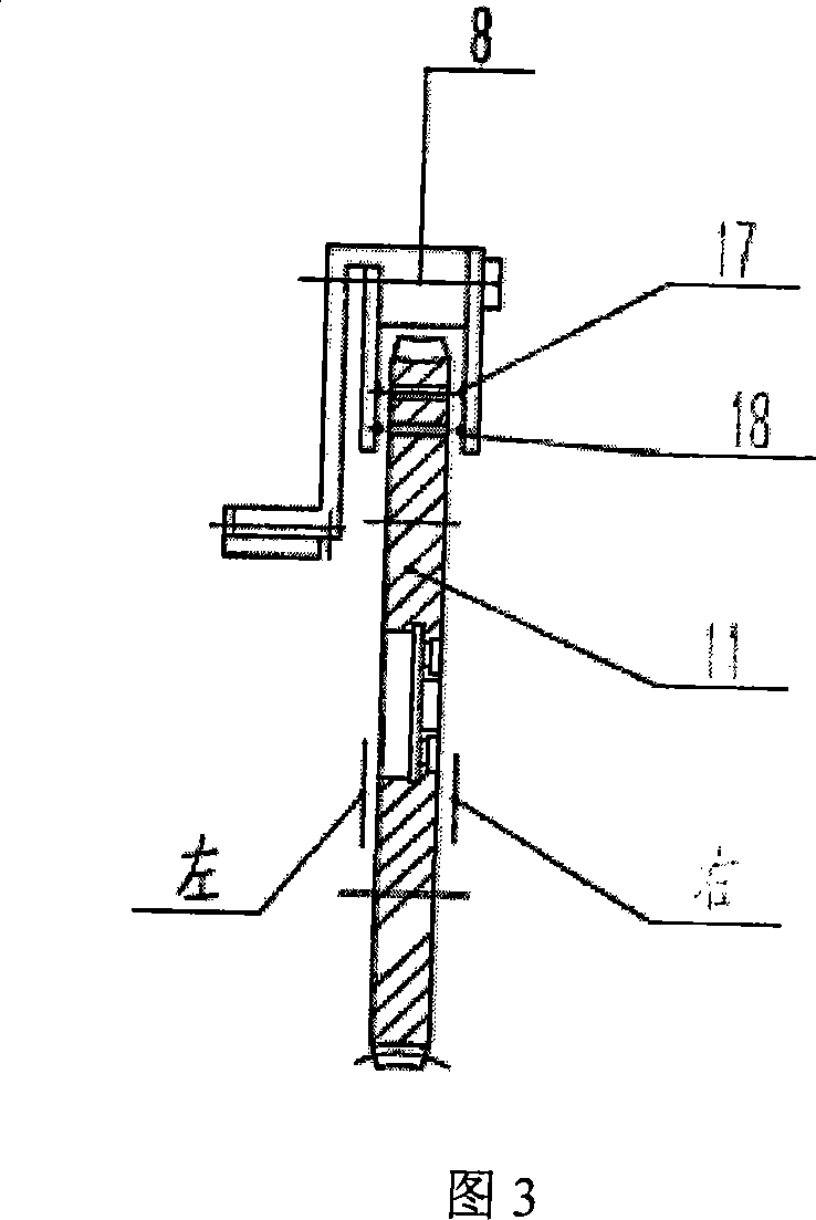
[0018] In this embodiment, 6 filters with different transmittances are selected, as shown in Figure 1 and Figure 2, the motorized filter light adjustment device in this embodiment includes: a support base 1, a pressing plate 2, a motor base 3, Dimming motor 4, bearing pressure ring 5, top screw 6, worm wheel rolling bearing 7, bent plate 8, worm rolling bearing 9, pressure ring 10, worm wheel 11, small shaft 12, hexagon socket head screw 13, cylinder head screw 14, cylinder Pin 15, worm screw 16, zero position diode pair tube 17, position diode pair tube 18, optical filter 19~24, cylinder head screw 25, cylinder head screw 26.

[0019] First fix the motor base 3 on the bottom plate of the instrument with the hexagon socket head screw 13, and then fix the dimming motor 4 on the motor base 3 with the cylindrical head screw 14, and the motor sha...


PUM


Abstract

A light adjusting device of electrical filter is characterized in that a motor base is fixed on a bottom plate of an instrument; a light adjusting motor is fixed on the motor base; a motor shaft on the light adjusting motor is connected with a worm which rotates on a worm rolling bearing; a worm wheel is fixed on a support base and rotates on a worm wheel rolling bearing; N round holes with identical diameters are uniformly formed on the worm wheel, N filters with different transmittances are inserted in the round holes and fixed on the worm wheel; a zero-position diode pair and a position diode pair are arranged on a bending plate on the worm wheel; the worm can rotate when the light-adjusting motor is electrified and is engaged with the worm wheel to drive the worm wheel to rotate, the position light emitting diode emits position signals during the rotation process of the worm wheel, and the position receiving diode receives the signals and transmits the signals to a light-adjusting motor controller to sequentially display the position of each filter. The invention changes the light adjustment manner of photoelectric instrument from single manual adjustment to electrical adjustment, thus satisfying the automatic requirement of modern optical instruments.

Description

technical field [0001] The invention relates to an electric filter mirror dimming device. Background technique [0002] Adding a filter to the optical system, its function is to attenuate various components of visible light at the same time, and the attenuation of each part is required to be as flat as possible. For example, a green filter is added to the observation instrument, which can filter out the atmosphere. Scattered violet-blue light to obtain yellow-green light with high sensitivity to human eyes; after adding a neutral filter to the strong light observation instrument to weaken the strong light, the contrast between the object and the background can be improved; thus better Clarity; but due to seasonal weather, high angle of the sun and scene features, as well as night and day changes, the intensity of incident light changes greatly, in order to obtain a clear image on the CCD, it is necessary to change the transmittance of the filter. gear dimming. However, sin...

Claims


Application Information

Patent Timeline
Patent Type & Authority Applications(China)
IPC IPC(8): G02B7/00G05B19/04
Inventor 李建凤张云珍任绍恒孟峰
Owner INST OF OPTICS & ELECTRONICS - CHINESE ACAD OF SCI
Why Eureka
Try Eureka