


Quick Research
Generate reliable direction feasibility study reports for your R&D in just a few steps.

Technical Q&A
Discover and master advanced knowledge NOW. Basics, ideas, possibilities, all at once.

Find Solutions
As an expert in R&D theories, this can generate solutions to your technical problems instantly.

Evaluate Feasibility
Analyze your overall solution with one click, know your potential R&D risks in advance.

Monitor Landscape
Get weekly tech updates, stay abreast of the latest tech innovations and key insights.
Chamber type limit self-tightening type seal
A self-tightening and limiting technology, applied in the direction of engine seals, engine components, mechanical equipment, etc., can solve the problem of poor self-limiting and positioning functions of box-type sealing devices, reducing the reliability of box-type equipment and the convenience of operation. It can reduce the processing difficulty and processing requirements, the structure is simple, and the processing requirements are low.
- Summary
- Abstract
- Description
- Claims
- Application Information
AI Technical Summary
Problems solved by technology
Method used
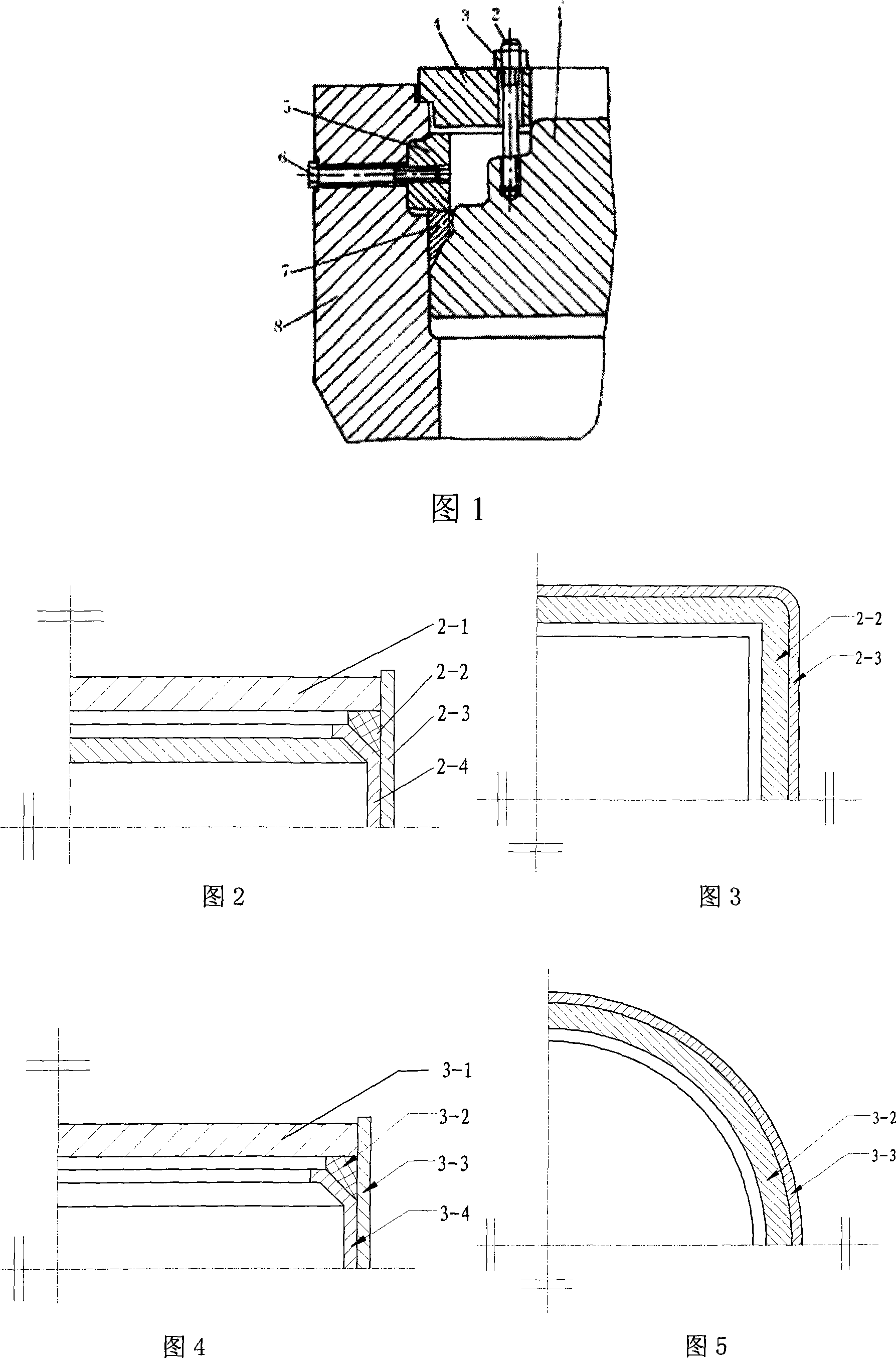
Image

Examples
Embodiment 1
[0023] Embodiment 1: In Fig. 2, the mechanical contact surface 2-1, the trapezoidal gasket 2-2, the mechanical outer shell 2-3, and the "Y" shaped waist strip 2-4. There is a right-angle "Y" groove on one flange face of the flange pair, a trapezoidal gasket, and the trapezoidal gasket is located in the right-angle "Y" groove of the flange. The other flange surface of the flange pair is a plane, and the right-angle "Y" groove on the flange surface is processed by a conventional milling machine. The mechanical housing is a square box, and the trapezoidal gasket corresponds to the square box.
Embodiment 2
[0024] Embodiment 2: The other flange surface of the flange pair is a curved surface, and the right angle "Y" groove on the flange surface is welded or spot welded with a flat plate and a matching "Y" waist strip. Others are the same as embodiment 1, omitted.
Embodiment 3
[0025] Embodiment 3: In Fig. 3, the mechanical contact surface 3-1, the trapezoidal gasket 3-2, the mechanical outer casing 3-3, and the "Y" shaped waist strip 3-4. The mechanical housing is a round box, and the trapezoidal gasket corresponds to the round box. Others are the same as embodiment 1, omitted.
PUM
 Abstract
Description
Claims
Application Information
 - R&D Engineer
- R&D Manager
- IP Professional
- Industry Leading Data Capabilities
- Powerful AI technology
- Patent DNA Extraction
Browse by: Latest US Patents, China's latest patents, Technical Efficacy Thesaurus, Application Domain, Technology Topic, Popular Technical Reports.
© 2024 PatSnap. All rights reserved.Legal|Privacy policy|Modern Slavery Act Transparency Statement|Sitemap|About US| Contact US: help@patsnap.com