
Heat insulation decoration board and its connecting component on site construction method

A technology for thermal insulation decorative panels and on-site construction, applied in covering/lining, architecture, building structure, etc., can solve the problems of high production cost, complex on-site installation process, numerous steps, etc., and achieve good decorative effect, simple and reasonable structure, Manipulate flexible effects

Inactive Publication Date: 2008-07-09
瞿浩荣
View PDF1 Cites 16 Cited by
  • Summary
  • Abstract
  • Description
  • Claims
  • Application Information

AI Technical Summary

Problems solved by technology

The prefabricated thermal insulation wallboard of this structure is expensive to manufacture because of the surrounding channel steel, and its on-site installation process is complicated and there are many steps

Method used


Image

  • Heat insulation decoration board and its connecting component on site construction method
  • Heat insulation decoration board and its connecting component on site construction method
  • Heat insulation decoration board and its connecting component on site construction method

Examples


no. 1 example

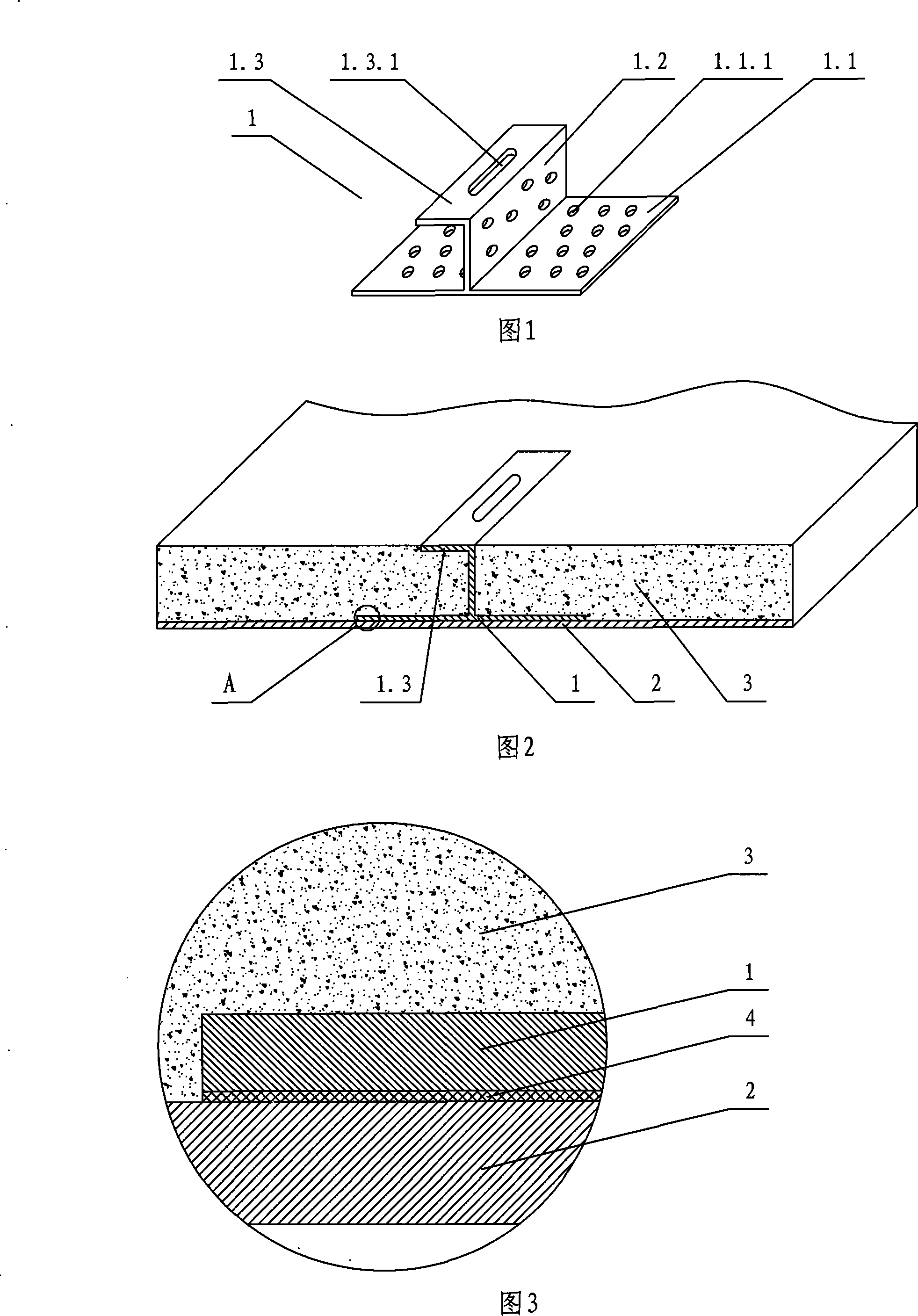
[0042] Referring to Fig. 1-Fig. 5, the thermal insulation decorative board and its connecting parts are embedded with one or more thin-walled first connecting parts 1, and the first connecting parts include the first horizontal bottom board 1.1. A vertical vertical board 1.2, the top of the first vertical vertical board is provided with a first horizontal fold 1.3, the first horizontal fold is arranged at right angles to the first vertical vertical board, the top surface of the first horizontal fold and the polyurethane layer 3 The upper surface is even, and the first positioning hole is provided on the first transverse flange, the first positioning hole is a strip hole 1.3.1 or a round hole 1.3.2, and the first transverse bottom plate and the first vertical vertical plate are provided with The first small hole for reinforcement 1.1.1. After the first horizontal fold 1.3 is bent outward, it is set at an obtuse angle with the first vertical vertical plate 1.2, the polyurethane ...

no. 2 example

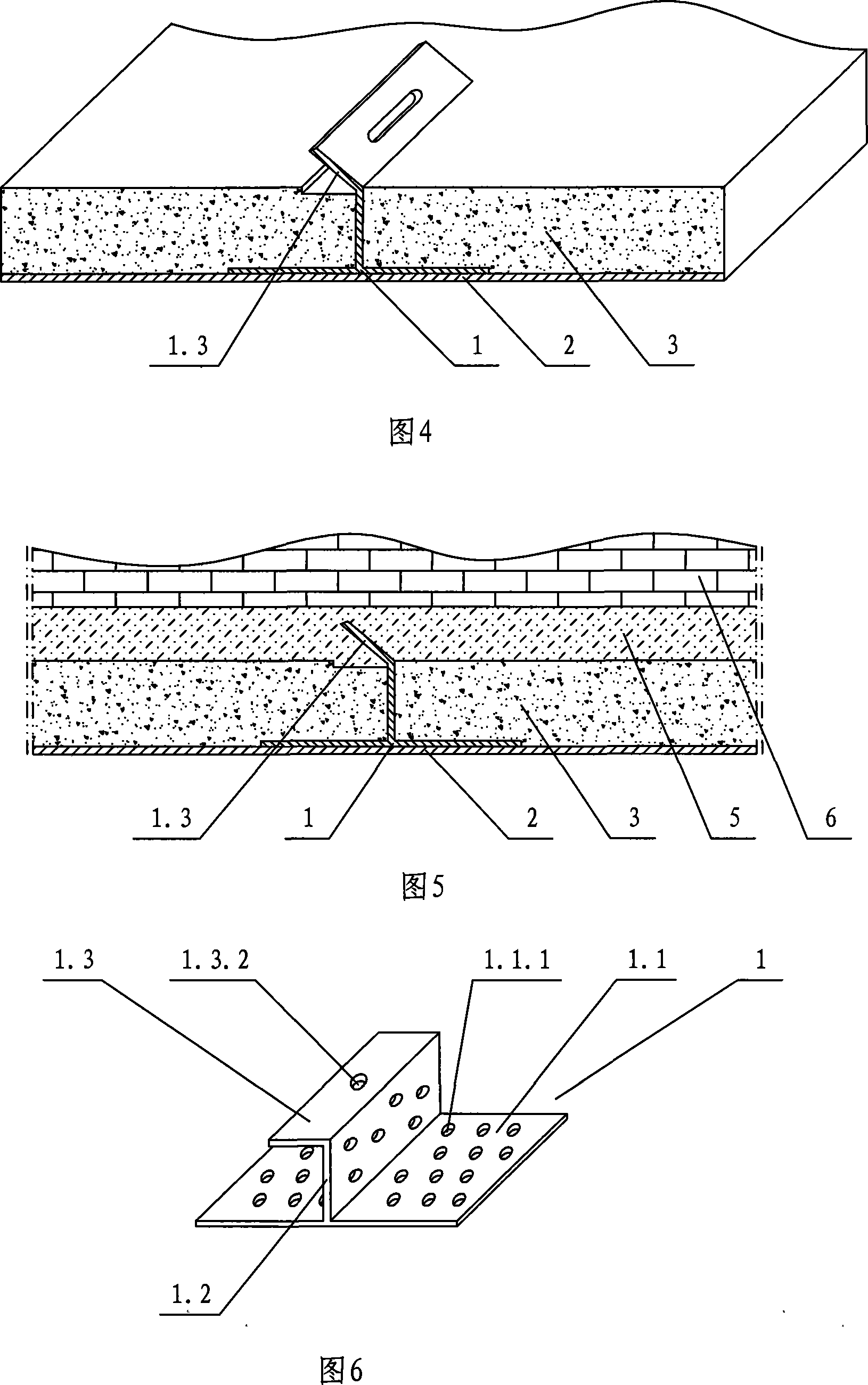
[0046]Referring to Fig. 6-Fig. 7, after the first transverse flange is bent outward, it is set at an obtuse angle with the first vertical vertical plate, and a short positioning rod 1.4 or a screw is arranged in the first positioning hole, and the short positioning rod or screw is connected with the second positioning hole. The transverse folds are arranged at an angle, the polyurethane layer of the thermal insulation decorative board is attached to the putty layer, and the second transverse fold and short positioning rods or screws are embedded in the putty layer together.

[0047] See the first embodiment for the rest of the undescribed parts, and will not repeat them here.

no. 3 example

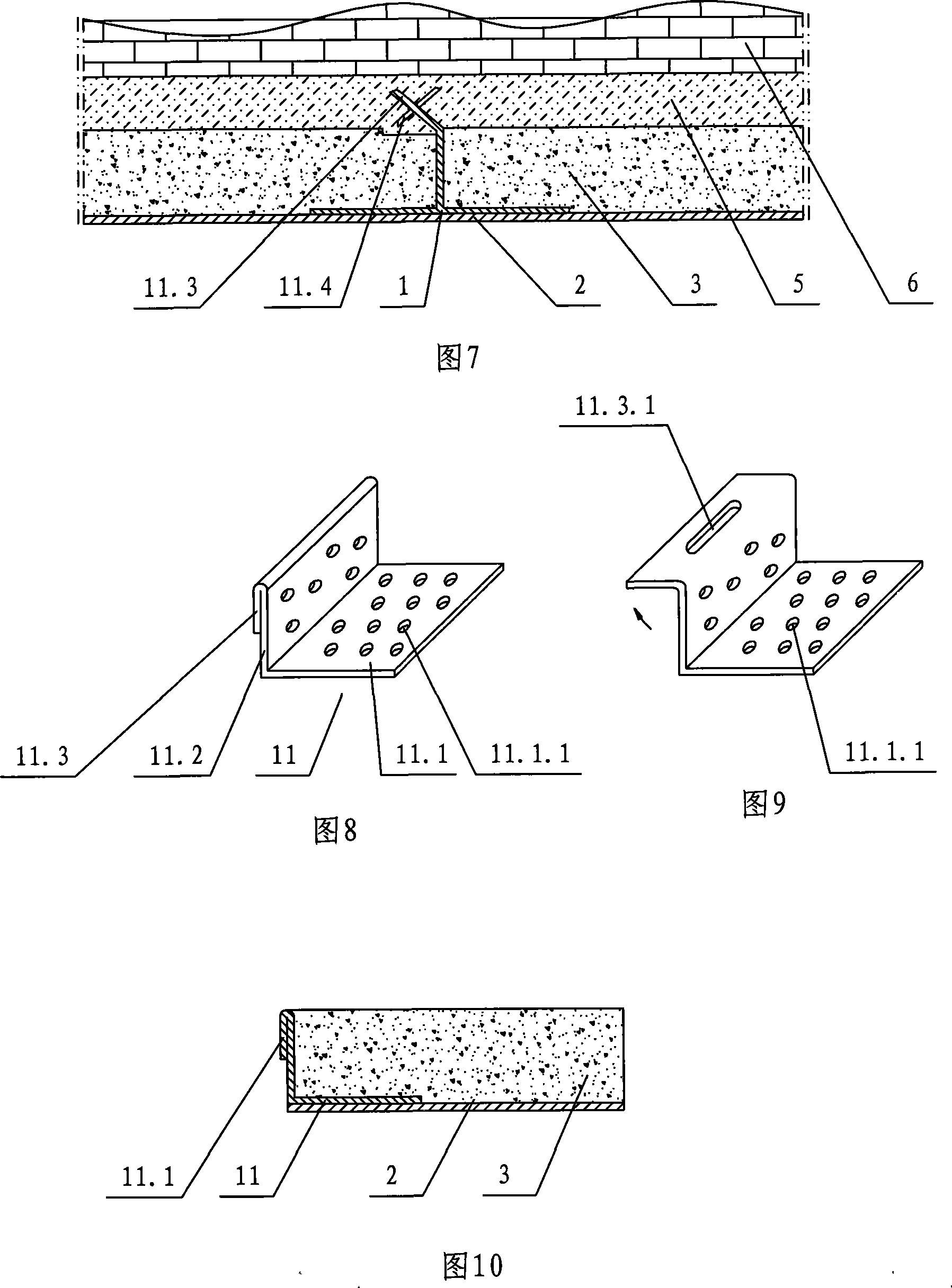
[0049] 8-10, the second connecting piece 11 includes a second vertical vertical plate 11.2 arranged on the second horizontal bottom plate 11.1, the end of the second vertical vertical plate is provided with a second transverse flange 11.3, the second The horizontal fold is close to the second vertical vertical plate, the highest point of the second vertical vertical plate and the second horizontal fold is flush with the upper surface of the polyurethane layer 3, and the second horizontal fold is provided with a second positioning hole 11.3.1 , the second connecting piece is arranged on the edge of the decorative substrate, the second vertical vertical plate is arranged outwardly, and the second transverse fold is arranged outwardly. The second transverse fold 11.3 is set at right angles to the second vertical vertical plate 11.2 after being folded, and the second transverse fold is laid on the putty layer 5, and the second transverse fold of two adjacent thermal insulation deco...


PUM


Abstract

The invention relates to a field construction method of a thermal insulation decorative sheet and a connecting piece of the thermal insulation decorative sheet, one or more than one connecting pieces with thin wall are inserted on the thermal insulation decorative sheet, the thermal insulation decorative sheet comprises a polyurethane coating which is arranged on a decorative base slab, wherein the lower end of the connecting piece is clung with the decorative base slab, the top is level to the upper surface of the polyurethane coating, the connecting piece comprises a transverse base slab, a vertical slab and a transverse edge fold, wherein a locating hole is arranged on the transverse edge fold. The connecting piece is a first connecting piece, the first connecting piece comprises a first vertical slab which is arranged on a first transverse base slab, a first transverse edge fold is arranged on the top of the first vertical slab, the first transverse edge fold and the first vertical slab are arranged in a right angle, the top surface of the first transverse edge fold is level to the upper surface of the polyurethane coating, a first locating hole is arranged on the first transverse edge fold, and the first locating hole is a strip-shaped hole or a round hole. The invention has the advantages of factory prefabrication, low fabricating cost, simple field construction and good wall surface decorative effects.

Description

technical field [0001] The invention relates to an on-site construction method of a thermal insulation decorative board for a wall and a connecting piece thereof. Background technique [0002] Chinese Patent Document No. CN2888001Y discloses a prefabricated thermal insulation wall panel, which is characterized in that it is composed of a wall panel, steel hooks and building sealant, the wall panel is made of thermal insulation material, surrounded by channel steel, The surface is covered with putty and spray-painted decorative layer, and the steel hook is composed of anchor bolt, anchor nut and hook rod. , the other end is connected with the anchor bolt nut, the hook rod passes through the connecting hole, and is worn on the anchor bolt rod, and the hook rod socket is arranged around the wallboard, and the two ends of the hitch rod are respectively inserted into two adjacent walls In the socket of the board, the gap formed between two adjacent wall boards is coated with bui...

Claims


Application Information

Patent Timeline
Patent Type & Authority Applications(China)
IPC IPC(8): E04F13/07E04F13/24B29C44/18E04F13/075
Inventor 瞿浩荣
Owner 瞿浩荣
Learn More