Eureka AIR delivers breakthrough ideas for toughest innovation challenges, trusted by R&D personnel around the world.

Large heavy workpiece lathe conveying device

A technology for handling devices and workpieces, applied in automatic/semi-automatic lathes, turning equipment, manufacturing tools, etc., can solve the problems affecting assembly accuracy and reliability, long clamping time, affecting the function of the whole machine, etc., to improve work efficiency, The effect of shortening clamping time and avoiding collisions

Inactive Publication Date: 2008-07-09
张琳
View PDF0 Cites 0 Cited by
  • Summary
  • Abstract
  • Description
  • Claims
  • Application Information

AI Technical Summary

Problems solved by technology

[0002] The handling of the workpiece not only affects the clamping efficiency of the workpiece on the lathe, but also has a great impact on the workpiece with precision requirements on the outer circle, and even affects the function of the whole machine
In the existing factory workshop, especially the workpieces with precision requirements on the outer circle are simply stacked together, so that during the handling process, due to the collision between the workpieces, the processed surface is damaged, which affects the assembly accuracy and reliability. At the same time, the large-weight workpiece is only moved from one position to another in the handling device. When the workpiece is clamped to the lathe, other auxiliary equipment such as a crane is needed. The clamping time is long and the work efficiency is low.
At the present stage, there is no device that has both the handling function and the position adjustment function.

Method used


Image

  • Large heavy workpiece lathe conveying device

Examples


Embodiment Construction

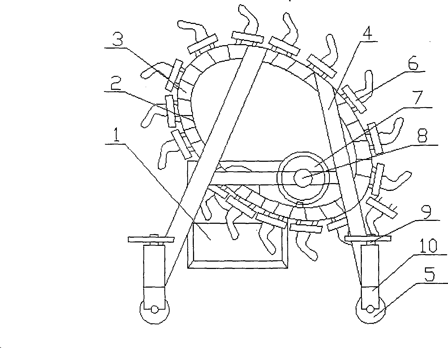
[0011] The accompanying drawing is an embodiment of the present invention, and this embodiment is described in detail in conjunction with the accompanying drawings, including a track 2, a transmission bar 3, a bracket 4, a fastening device 6, a transmission wheel 7, a handle 8, a universal wheel bracket 10 and a universal To the wheel 5, the track 2 is set to an ellipse and one side is provided with an inner groove, the track 2 is set to two and is arranged on the two ends of the transmission bar 3 and is arranged to be fixedly connected with the bracket 4, and the transmission bar 3 is set to multiple pieces and It is bar-shaped and arranged in the inner groove of the track 2, the transmission wheel 7 is set as a gear, the transmission wheel 7 and the handle 8 are set to be fixedly connected with the bracket 4 through a fixed shaft and the handle 8 is set to be fixedly connected to the transmission wheel 7, and the transmission wheel 7 is set to be connected with the inner sid...


PUM


Abstract

A heavy workpiece-carrying device of a lathe comprises tracks (2), driving strips (3), a supporting frame (4), tighteners (6), a driving wheel (7), a handle (8), universal wheel supporters (10) and universal wheels (5), wherein, one side of each elliptic track (2) is provided with an internal groove, the two tracks (2) are arranged on both ends of the driving strips (3) and firmly jointed with the supporting frame (4), the strip-shaped driving strips (3) are arranged in the internal grooves of the tracks (2), the driving wheel (7) and the handle (8), which are firmly jointed together, are firmly jointed with the supporting frame (4), the driving wheel (7) is jointed with the inner sides of the driving strips (3) by a tooth which is arranged at the joint between the driving strips (3) and the driving wheel (7), the tighteners are arranged on and firmly jointed with the outer sides of the driving strips (3), and the universal wheels (5) are firmly jointed with the universal wheel supporters (10), which are slidingly jointed with the supporting frame (4). Consequently, the present invention has the advantages of simple structure, convenient clamping, no need of a hoisting machine, no damage of workpieces and high working efficiency.

Description

1. Technical field [0001] The invention relates to a handling device for a workpiece in a factory workshop, in particular to a handling device for a large-weight workpiece lathe. 2. Background technology [0002] The handling of the workpiece not only affects the clamping efficiency of the workpiece on the lathe, but also has a great impact on the workpiece with precision requirements on the outer circle, and even affects the function of the whole machine. In the existing factory workshop, especially the workpieces with precision requirements on the outer circle are simply stacked together, so that during the handling process, due to the collision between the workpieces, the processed surface is damaged, which affects the assembly accuracy and reliability. At the same time, the large-weight workpiece is only moved from one position to another in the handling device. When the workpiece is clamped to the lathe, other auxiliary equipment such as a crane is needed. The clamping ...

Claims


Application Information

Patent Timeline
IPC IPC(8): B23Q7/00B23B13/00
Inventor 张琳
Owner 张琳
Why Eureka
Eureka Blog
Learn More