
Magnetic drive

A magnetic motive and magnetic ring technology, applied in the direction of generators/motors, electrical components, etc., can solve the problems of complex structure, no magnetic motive, and the power cannot meet the requirements of supporting equipment, and achieve the effect of protecting the ecological environment.

Inactive Publication Date: 2008-07-02
龚清
View PDF0 Cites 5 Cited by
  • Summary
  • Abstract
  • Description
  • Claims
  • Application Information

AI Technical Summary

Problems solved by technology

[0002] The acquisition of existing mechanical energy is converted by consuming water, electricity, oil, coal, gas, and nuclear energy. Such a result directly leads to the collapse of natural resources and the destruction of the ecological environment. Magnetic motors convert magnetic energy into mechanical energy , the development of the existing magnetic motor still exists in the technical conception, its structure is complex, the energy consumption between the magnets is too large, the power cannot meet the requirements of the required supporting equipment, and there is no magnetic motor that can adjust the speed

Method used


Image

  • Magnetic drive
  • Magnetic drive
  • Magnetic drive

Examples


Embodiment 1

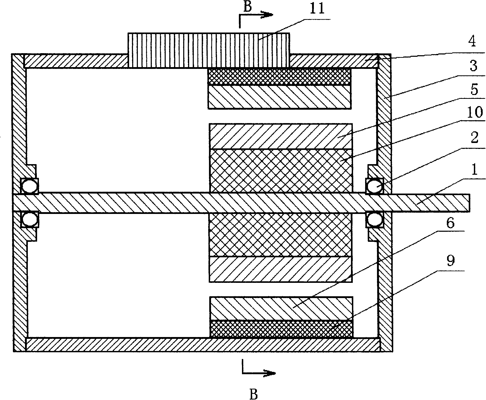
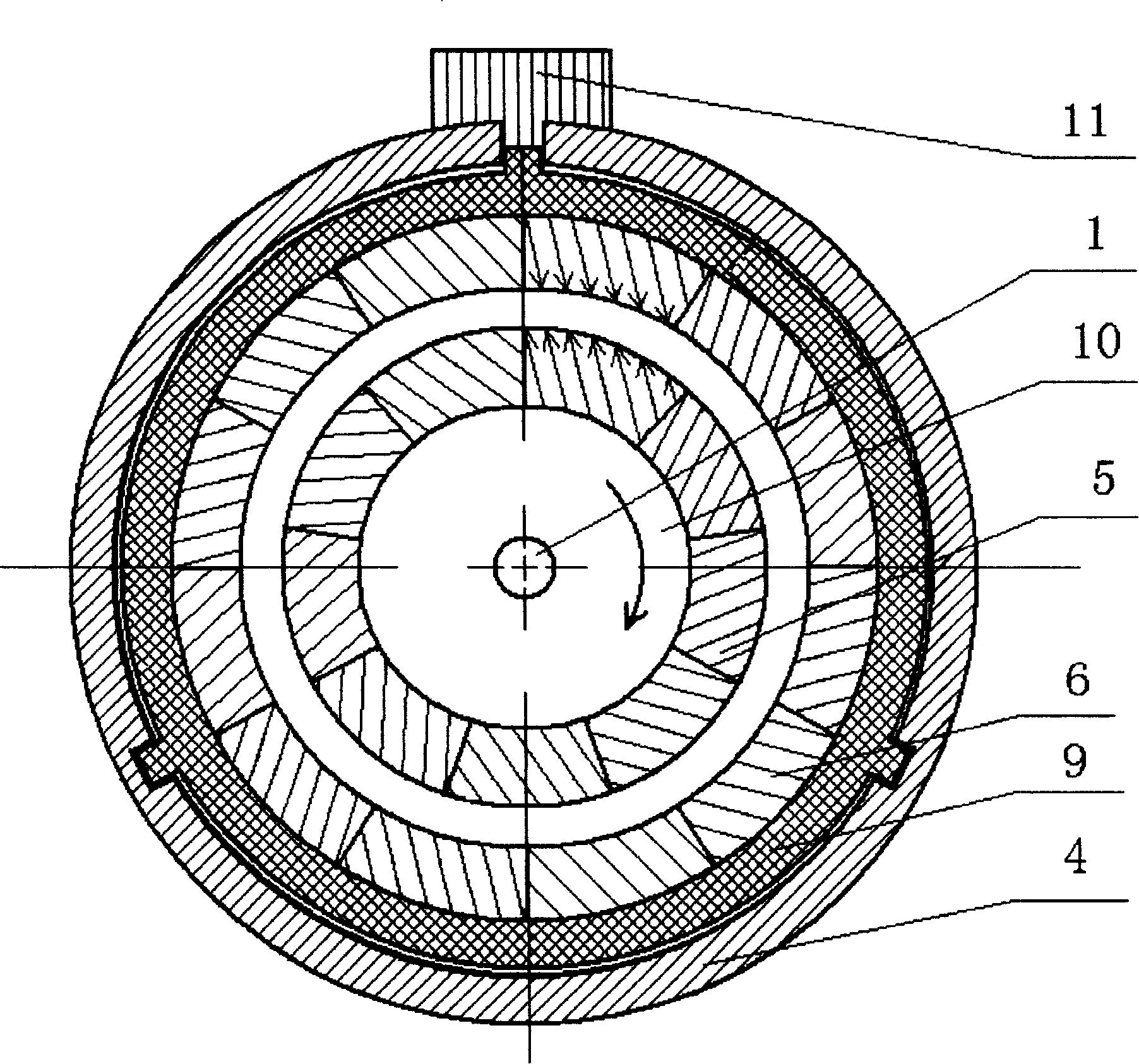
[0026] Such as figure 1 The magnetic motor shown is composed of a rotor assembly a, a stator assembly b, a bearing seat 3, a casing 4, and a speed regulating and positioning device 11, and its characteristics are: the rotor assembly a passes through the bearing seat 3 and is installed on the casing 4 The two ends of the rotor make the rotor circular magnetic ring 5 suspended in the stator circular magnetic ring 6. The speed regulating and positioning device 11 is connected with the stator assembly b through the concave rail at the upper end of the housing 4 . The stator assembly can be moved and positioned along the axial direction in the concave rail of the housing.

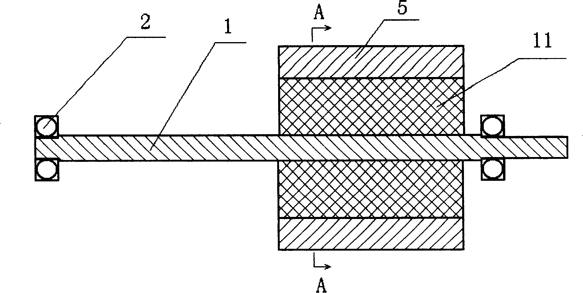
[0027] The rotor assembly a is composed of a rotating shaft 1, a bearing 2, a rotor circular magnetic ring 5, and an inner bushing 10, and is characterized in that: the rotor circular magnetic ring 5 is fixedly connected to the rotating shaft 1 through the inner bushing 10, and There are bearings 2.

[0028] ...

Embodiment 2

[0037] According to the above principles, multiple sets of magnetic power units can also be installed to generate greater power.


PUM


Abstract

The invention belongs to a power machine field and particularly relates to a magnetic motor. The invention comprises a rotor component, a stator component, a bearing seat and a shell and is characterized by no consumption of natural resource, no environmental pollution, no requirement on added energy source, attractive appearance, simple structure, convenient operation and maintenance, low cost, as well as easiness in market promotion and popularization.

Description

technical field [0001] The invention belongs to the field of power machinery, in particular to a magnetic power machine. Background technique [0002] The acquisition of existing mechanical energy is converted by consuming water, electricity, oil, coal, gas, and nuclear energy. Such a result directly leads to the collapse of natural resources and the destruction of the ecological environment. Magnetic motors convert magnetic energy into mechanical energy , the development of the existing magnetic motor still exists in the technical assumption, its structure is complicated, the mutual consumption of energy between the magnets is too large, the power cannot reach the requirements of the required supporting equipment, and there is no magnetic motor that can adjust the speed. Contents of the invention [0003] The object of the present invention is to manufacture a magnetic motor that does not require external energy, and can adjust the rotational speed of the magnetic motor a...

Claims


Application Information

Patent Timeline
Patent Type & Authority Applications(China)
IPC IPC(8): H02N11/00
Inventor 龚清
Owner 龚清
Learn More