
Fuel cell system

A fuel cell system and fuel cell technology, applied in the direction of fuel cells, fuel cell additives, control/regulation systems, etc., can solve problems such as capacitor deterioration and discharge device damage, prevent backflow, improve power generation utilization, and increase power The effect of utilization

Inactive Publication Date: 2008-06-25
OMRON CORP
View PDF5 Cites 8 Cited by
  • Summary
  • Abstract
  • Description
  • Claims
  • Application Information

AI Technical Summary

Problems solved by technology

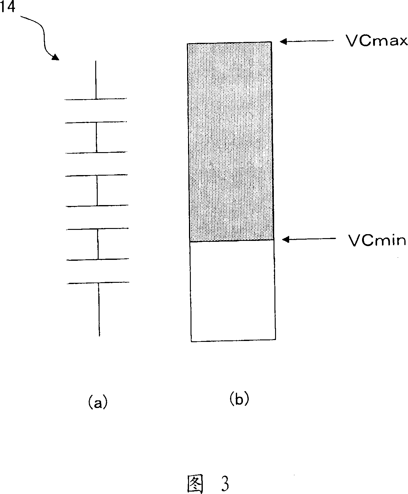
[0008] In a fuel cell system incorporating a charging / discharging device using a capacitor, if it is charged to a capacitor withstand voltage (capacitor voltage upper limit) or discharged to a capacitor discharge depth (capacitor voltage lower limit) or below, a The problem of deteriorating the capacitor due to damage to the discharge device

Method used


Image

  • Fuel cell system
  • Fuel cell system
  • Fuel cell system

Examples


Embodiment Construction

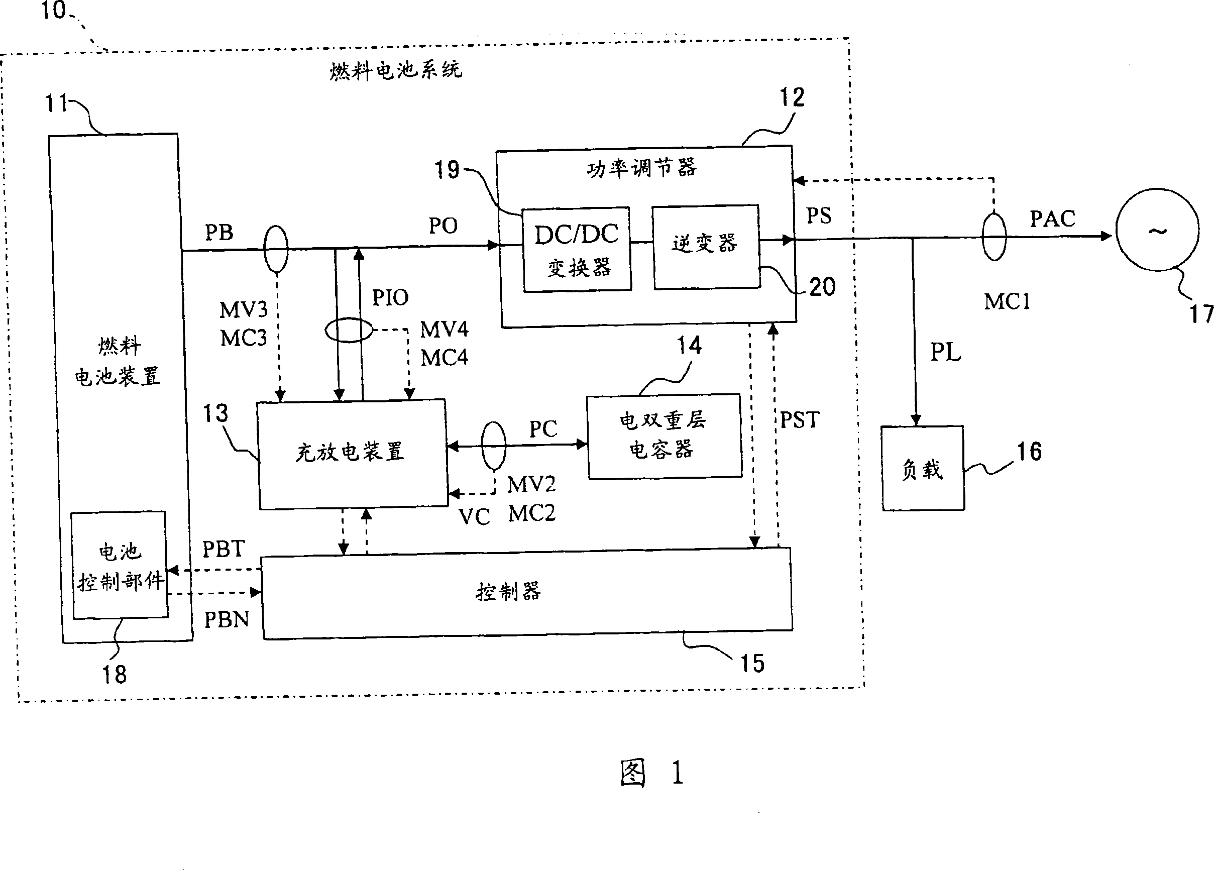
[0032] Hereinafter, a fuel cell system according to an embodiment of the present invention will be described with reference to the drawings. In addition, the power conversion between the charging and discharging device and the power conditioner (including the built-in DC / DC converter and inverter) actually produces losses, but for the sake of simplicity, the losses are ignored, assuming that the input and output power of the charging and discharging device are equal ( PIO = PC), and the input and output power of the power regulator are also equal (PO = PS) to illustrate.

[0033] FIG. 1 shows a schematic configuration of a fuel cell system 10 . 11 is a fuel cell device, 12 is a power regulator, 13 is a charging and discharging device, 14 is an electric double layer capacitor, 15 is a controller, 16 is a load, and 17 is a commercial power supply (system).

[0034] The fuel cell device 11 provides the direct current output (battery power) of the fuel cell, and includes the foll...


PUM


Abstract

The fuel cell system includes a fuel cell; a power conditioner that converts a cell power supplied from the fuel cell to a power corresponding to a load; a capacitor to which an excessive output power of the fuel cell is charged at the time of a low load operation and from which a power corresponding to the insufficient output power of the fuel cell is discharged at the time of a high load operation; a voltage detection means for detecting a voltage of the capacitor; and a control means that determines the low load operation or the high load operation, calculates an output power from the fuel cell to maintain the excessive power generated at the time of the low load operation within a space capacity of the capacitor, and controls the output power of the fuel cell not to exceed the calculated value.

Description

technical field [0001] The present invention relates to a domestic fuel cell system using a fuel cell. A fuel cell does not burn hydrogen and oxygen directly, but generates electricity by taking out electrons to an external circuit by electrochemically reacting at a fuel electrode and an air electrode separated by an electrolyte. Background technique [0002] As a fuel cell system, it has been proposed (for example, refer to Patent Document 1) that the fuel cell output is made to match the load power (power consumed by the load) in order to prevent backflow to a commercial power supply. This fuel cell system has an apparatus including: a fuel cell power supply that supplies power of a fuel cell; a power conversion unit that converts battery power into power corresponding to a load and outputs it to the load side; and controls the fuel cell power supply and the power conversion unit control parts. The fuel cell power source includes: a reformer that changes the property of ...

Claims


Application Information

Patent Timeline
Patent Type & Authority Applications(China)
IPC IPC(8): H01M8/00H02M3/155H02M3/28
CPCH02J3/387H02J2001/004H02J2300/30H02J3/381Y02E60/50H01M8/04
Inventor 村林阳康
Owner OMRON CORP
Learn More