
Method for measuring air leakage in mine

A technology of air leakage and mine, which is applied in the direction of measuring device, measuring flow/mass flow, liquid/fluid solid measurement, etc., which can solve the problems of unmeasured air leakage and high gas cost

Inactive Publication Date: 2008-06-18
CHINA SHENHUA ENERGY CO LTD
View PDF0 Cites 21 Cited by
  • Summary
  • Abstract
  • Description
  • Claims
  • Application Information

AI Technical Summary

Problems solved by technology

SF 6 The gas measurement method still has great limitations. It can only be used when the air leakage increases the air volume of the air flow, and the air leakage in other cases cannot be measured.
Simultaneous determination of SF 6 The cost of gas is very high, and special gas chromatographs and analysis methods are required, which are rarely used in practice

Method used


Image

  • Method for measuring air leakage in mine

Examples


Embodiment Construction

[0026] To illustrate the method, the following example illustrates the principle of the method:

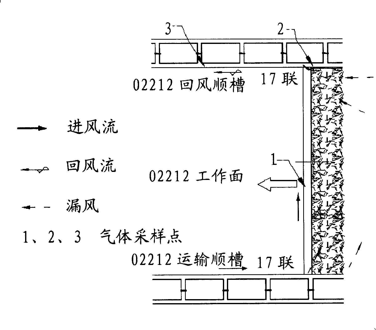
[0027] see figure 1 , taking a coal mine 02212 as an example, the air leakage value of the coal mine was measured.

[0028] 1. Measure the air volume Q at the mining face, the gas concentration at the mining face A1, the air leakage gas concentration A2, and the return air flow at the working face (that is, after the gas at the mining face and the air leakage gas are merged and mixed) the gas concentration A3:

[0029] The air intake Q of the fully mechanized mining face is 2330m 3 / min; three gas sampling points 1, 2, and 3 shown in the figure were selected for gas sampling, and sampling point 1 was located in the air inlet flow stope space of the fully mechanized mining face.

[0030] Gas analysis was carried out by gas chromatography.

[0031] Here, any existing technology can be used to measure the air intake Q of the fully mechanized mining face; gas chromatograph can be u...


PUM


Abstract

The invention provides a method of measuring the air leakage rate inside mines, in particular in coal mines. The method comprises steps of measuring the air flow Q at the upstream of the air leakage area, the air concentration A1 at the upstream of the air leakage area, the air concentration A2 of the air leakage area, and the air concentration A3 at the downstream of the air leakage area; the invention also comprises the steps of calculating the air leakage rate according to the formula: Q1=Q*(A3-A1) / (A2-A3). The method has the characteristics of handiness and economy, and meets the requirements to measure air leakage rate inside various mines.

Description

technical field [0001] The invention relates to a method for measuring air leakage, in particular to a method for measuring air leakage in various goafs in mines. Background technique [0002] In the mining industry, especially in the coal mining industry, after the coal mining is completed, a goaf will be formed. On the one hand, the upper rock layer of the coal seam will cascade or produce cracks, and surface subsidence will occur; Continuously moving forward, the goaf formed behind the coal mining face cannot be compacted due to the roof falling, forming an air leakage channel; After sealing, due to the lax sealing and the existence of loose rings of surrounding rocks, an air leakage channel is formed. While the mine ventilator is ventilating the whole mine underground and the effect of natural wind pressure, a wind pressure difference is generated at both ends of these air leakage channels, thereby causing a small amount of air flow to flow through the goaf, that is, th...

Claims


Application Information

Patent Timeline
Patent Type & Authority Applications(China)
IPC IPC(8): G01F1/00G01F1/704
Inventor 周成军
Owner CHINA SHENHUA ENERGY CO LTD
Learn More