
Pressure regulating valve

A pressure regulating valve and pressure regulating technology, applied in the direction of safety valves, balance valves, valve devices, etc., can solve the problems of unstable gas flow, easy deviation of the center of the diaphragm, and air leakage of the pressure regulating valve, etc., to achieve stable gas flow , good pressure regulation effect and reasonable structure

Active Publication Date: 2008-06-18
NINGBO AIRTAC AUTOMATIC INDAL
View PDF0 Cites 18 Cited by
  • Summary
  • Abstract
  • Description
  • Claims
  • Application Information

AI Technical Summary

Problems solved by technology

[0003] The present invention provides a pressure regulating valve with a fixed diaphragm center and stable gas flow in order to solve the problem that the center of the diaphragm in the current pressure regulating valve is easily shifted, resulting in air leakage of the pressure regulating valve and resulting in unstable gas flow.

Method used


Image

  • Pressure regulating valve
  • Pressure regulating valve

Examples


Embodiment 1

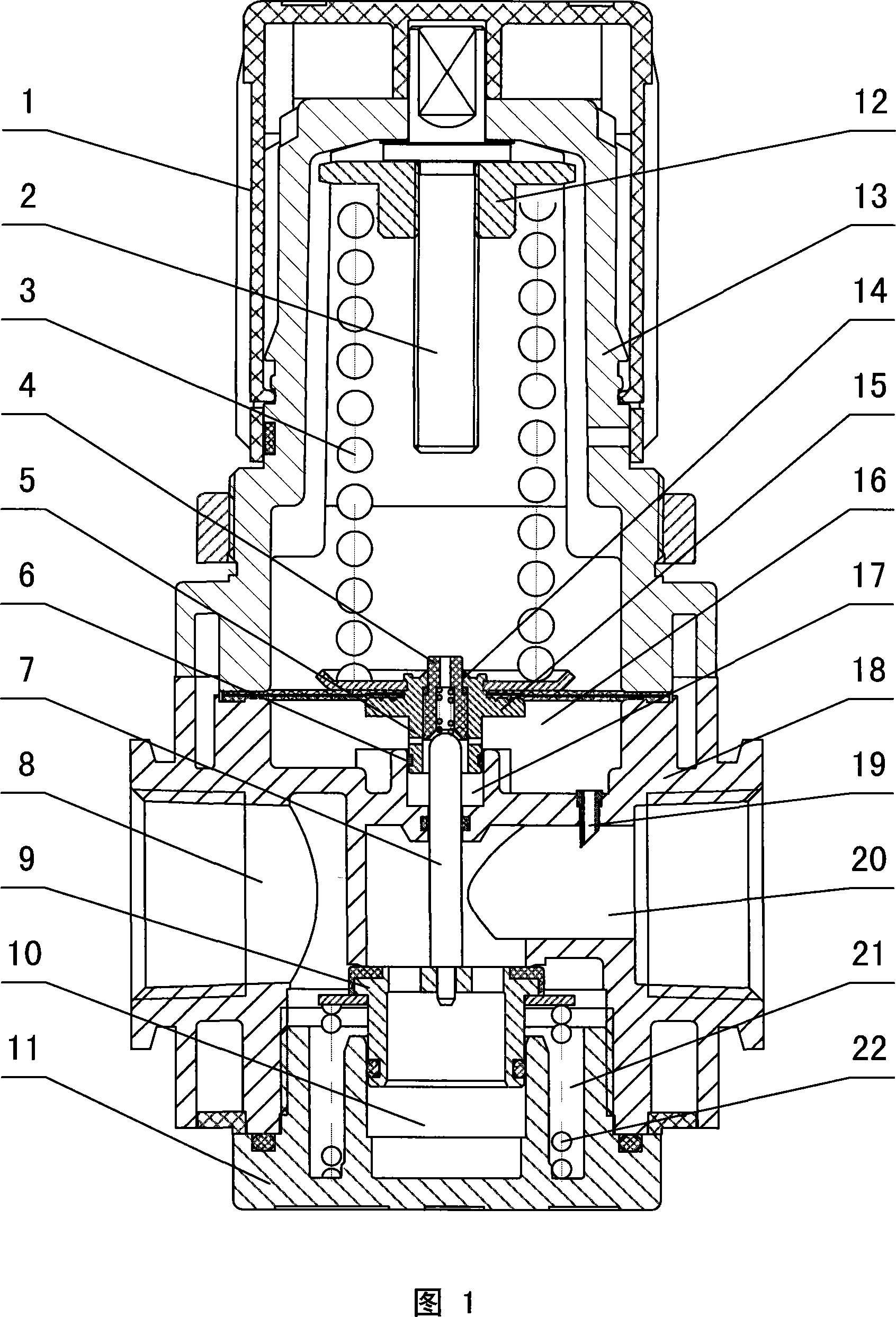
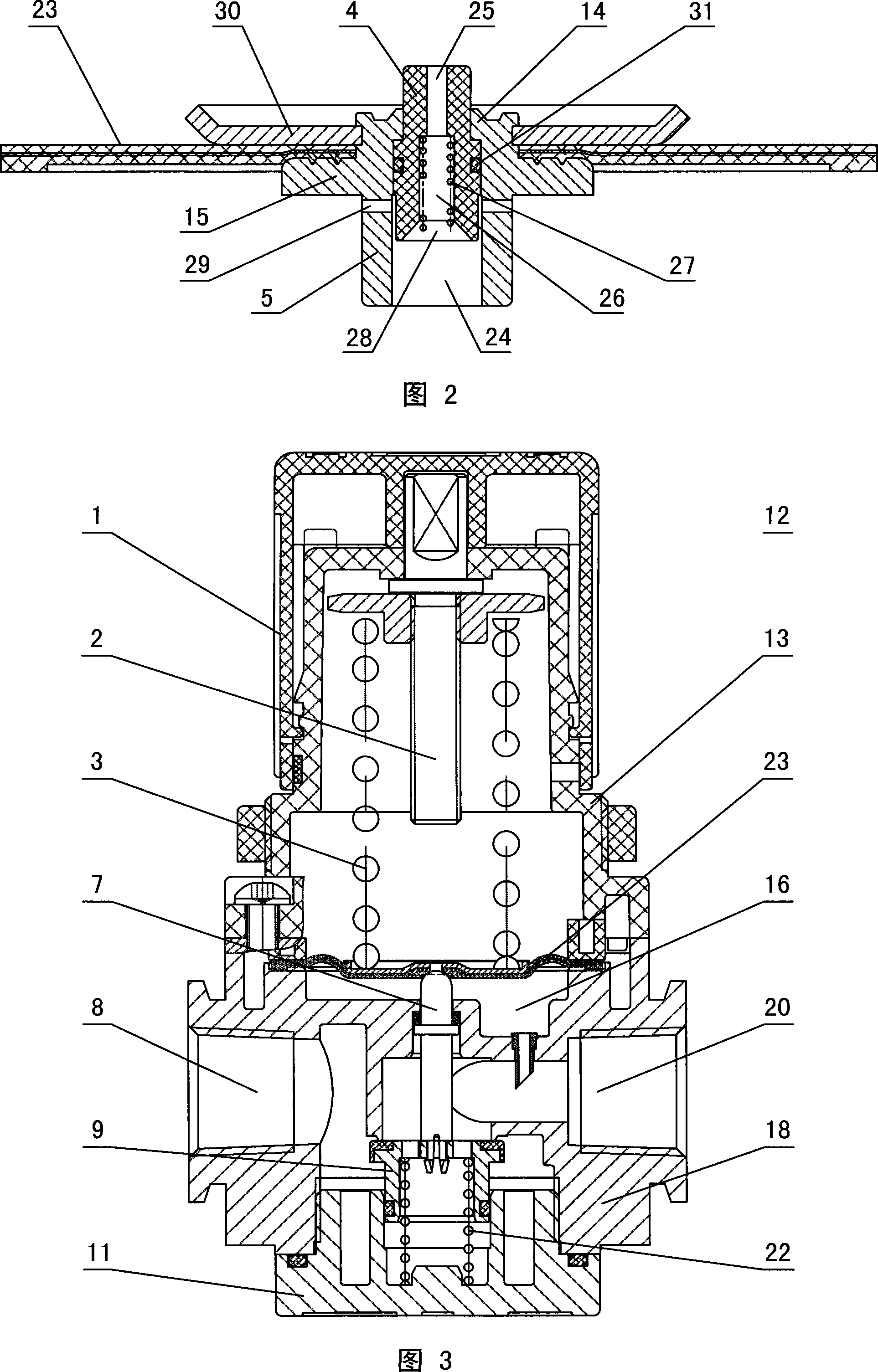
[0020] In the embodiment 1 shown in Figure 1 and Figure 2, the body 18 of the pressure regulating valve is provided with an air inlet 8 and an air outlet 20, and a valve cap 11 is provided under the body 18, and a valve cap 11 and the body 18 are provided with Threaded connection, the valve cap 11 is provided with a plug chamber 10 that is compatible with the pressure regulating plug 9, and the piston part at the lower end of the pressure regulating plug 9 extends into the plug chamber 10. The outside of the plug cavity 10 is provided with an annular groove 21, and a plug spring 22 is arranged in the annular groove 21. The upper end of the plug spring 22 is connected to the pressure regulating plug 9, and the lower end is fixed at the bottom of the annular groove 21. The bonnet 11 Sealing rings are arranged between the body 18 and the valve cap 11 and the piston of the pressure regulating plug 9 . The pressure regulating seat 13 is arranged on the top of the body 18, and its t...


PUM


Abstract

The invention discloses a pressure regulating valve. The body of the pressure regulating valve is provided with an air inlet and an air outlet. A valve cap is arranged under the body and the valve cap is provided with a pressure regulating choke plug. A pressure regulating seat is arranged on the upper surface of the body. The top end of the pressure regulating seat is a pressure regulating button. An elastic membrane body is arranged between the pressure regulating seat and the body. The central of the elastic membrane body is provided with a mebrane seat. The upper end of the mebrane is fixed with a mebrane and the lower end is provided with a guiding shaft. The central of the mebrane is a sealing cavity. The upper part of the sealing cavity is provided with a sealing plug with an air discharge hole. The upper part of the body is provided with a guiding cavity. The guiding shaft on the mabrane seat and the guiding cavity on the body form a moving pair. The invention effectively solves the problems exited in the current pressure regulating valve that the center of the mabrane is easy to deviate and the air flow is not stable enough. The invention has the advantages of reasonable design, stable air flow, good pressure regulating effect and long service life. The quality of the pressure regulating valve has been improved remarkably.

Description

technical field [0001] The invention relates to a pressure regulating device for automatically regulating gas pressure, in particular to a pressure regulating valve with a fixed diaphragm center and stable gas flow. Background technique [0002] Pressure regulating valves are widely used in light industry, chemical industry, petroleum, natural gas and other gas transmission occasions. Attachment 3 is a schematic structural diagram of a traditional pressure regulating valve. When the pressure regulating button on the upper end of the pressure regulating valve is loosened, the main spring is not under pressure. , the pressure regulating plug is lifted upwards under the action of the plug spring, the flow path between the pressure regulating plug and the pressure regulating valve body is sealed, the airflow from the left air inlet cannot reach the right air outlet, the pressure regulating valve is off. When the pressure regulating knob is tightened, the main spring is forced t...

Claims


Application Information

Patent Timeline
IPC IPC(8): F16K17/04G05D16/06
Inventor 王世忠
Owner NINGBO AIRTAC AUTOMATIC INDAL
Learn More