Gas path pressure release device and corresponding gas path pressure release device realizing large pressure reducing ratio

A decompression device and gas circuit technology, applied in the direction of valve device, fluid pressure control without auxiliary power, safety valve, etc., can solve the problems of cumbersome adjustment of decompression spring, large valve body diameter, unsuitable use, etc., to achieve Good pressure stabilizing effect, good sealing effect, reduced volume and mass

Active Publication Date: 2011-06-22
CAMA LUOYANG GAS SUPPLY
View PDF1 Cites 0 Cited by
  • Summary
  • Abstract
  • Description
  • Claims
  • Application Information

AI Technical Summary

Problems solved by technology

In order to open the valve port, the decompression spring must provide a large force to the piston, and once the valve port is opened, the upper end surface of the T-shaped valve will also be affected by high-pressure gas, which will increase the opening of the valve port. In order to achieve a good decompression effect, sometimes it is necessary to return the decompression spring to reduce the opening of the valve port, which makes the adjustment of the decompression spring very cumbersome
At the same time, in order to stabilize the outlet pressure in order to obtain a stable decompression ratio, it is necessary to realize the dynamic balance of the pressure reducer, that is, when the outlet pressure is high, the piston will move upward, the valve port will be closed, and the outlet pressure will become smaller. If it is too small, the piston will move downwards, the valve port will open larger, and the outlet pressure will increase. To achieve such a dynamic balance, it is necessary to make the lower surface of the piston in contact with the outlet gas larger than the upper surface of the T-shaped valve in contact with the outlet gas. The diameter of the piston will be larger, resulting in a larger diameter of the entire valve body, making it unsuitable for occasions with small installation space, and the larger mass will also make it unsuitable for use in occasions with quality requirements, such as some aircraft.

Method used


Image

  • Gas path pressure release device and corresponding gas path pressure release device realizing large pressure reducing ratio
  • Gas path pressure release device and corresponding gas path pressure release device realizing large pressure reducing ratio
  • Gas path pressure release device and corresponding gas path pressure release device realizing large pressure reducing ratio

Examples


Embodiment Construction

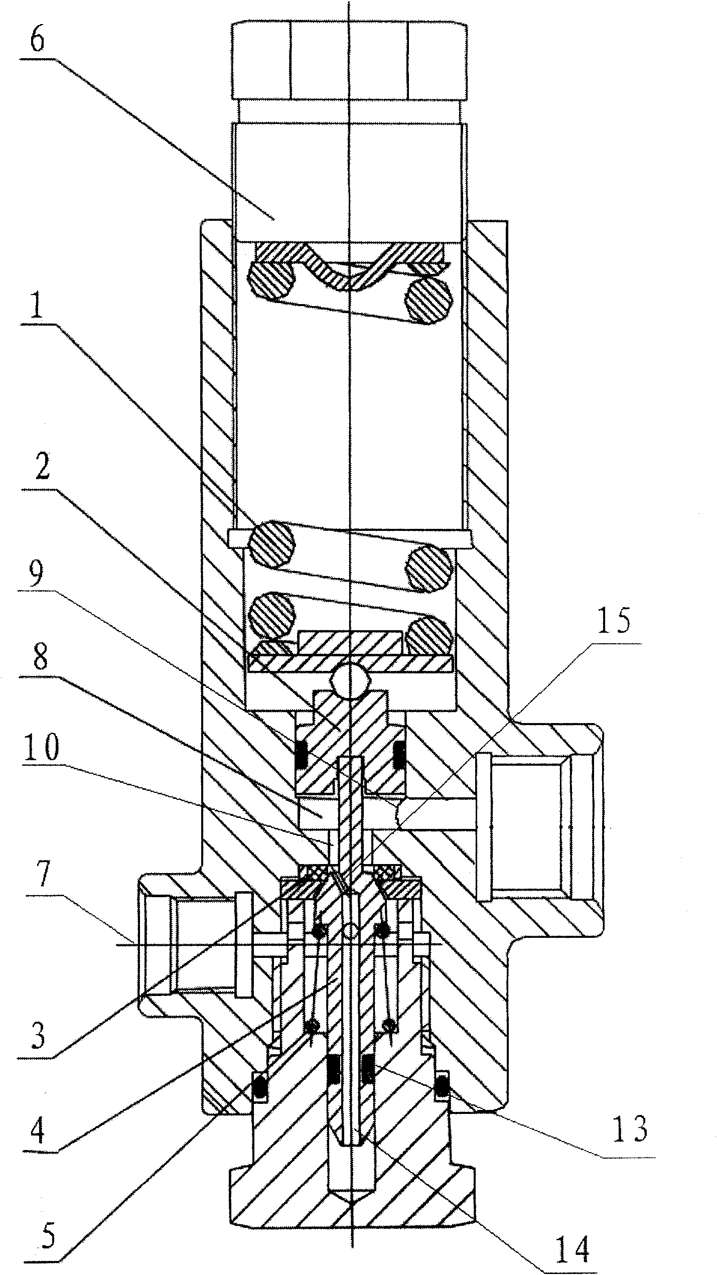
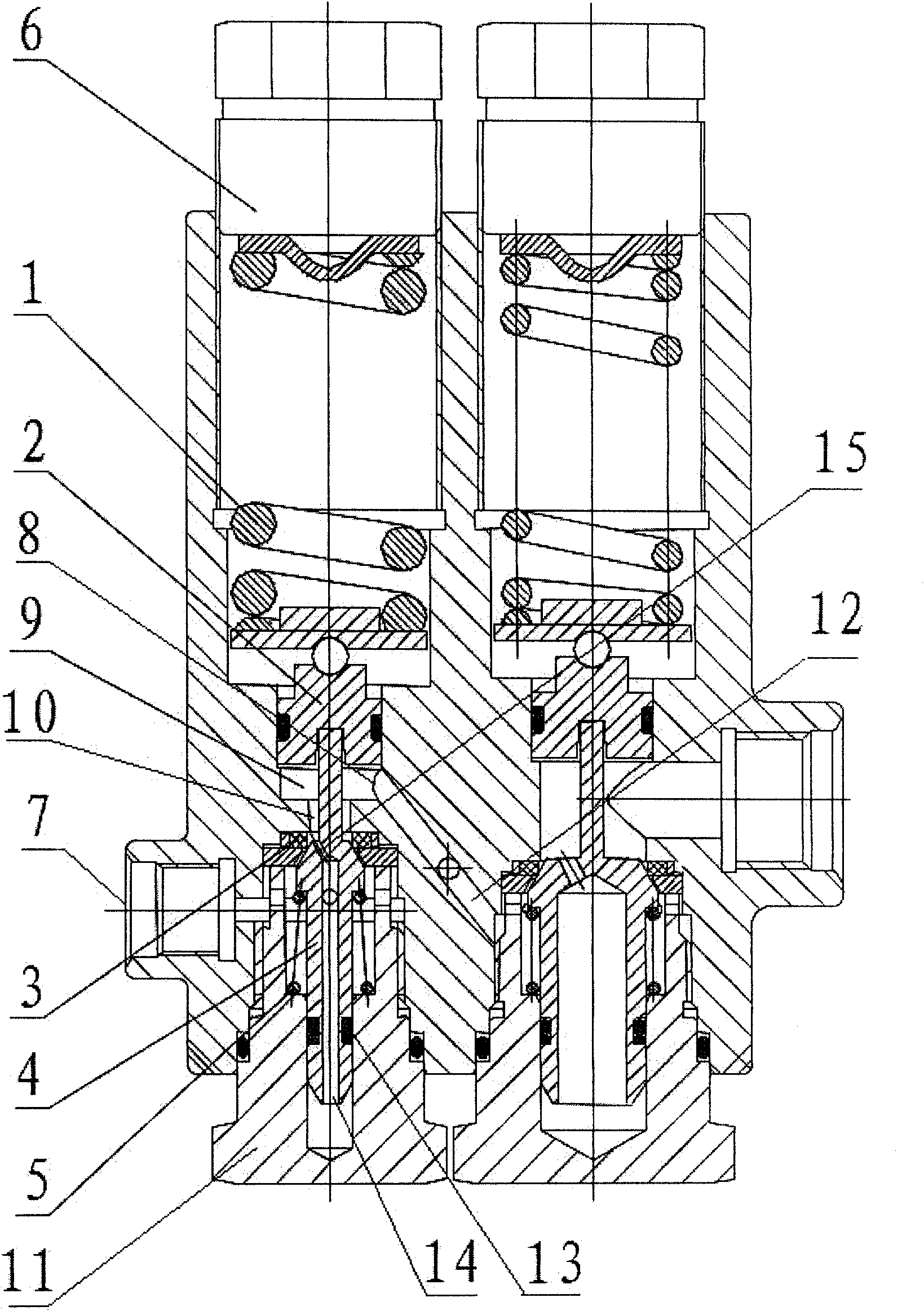
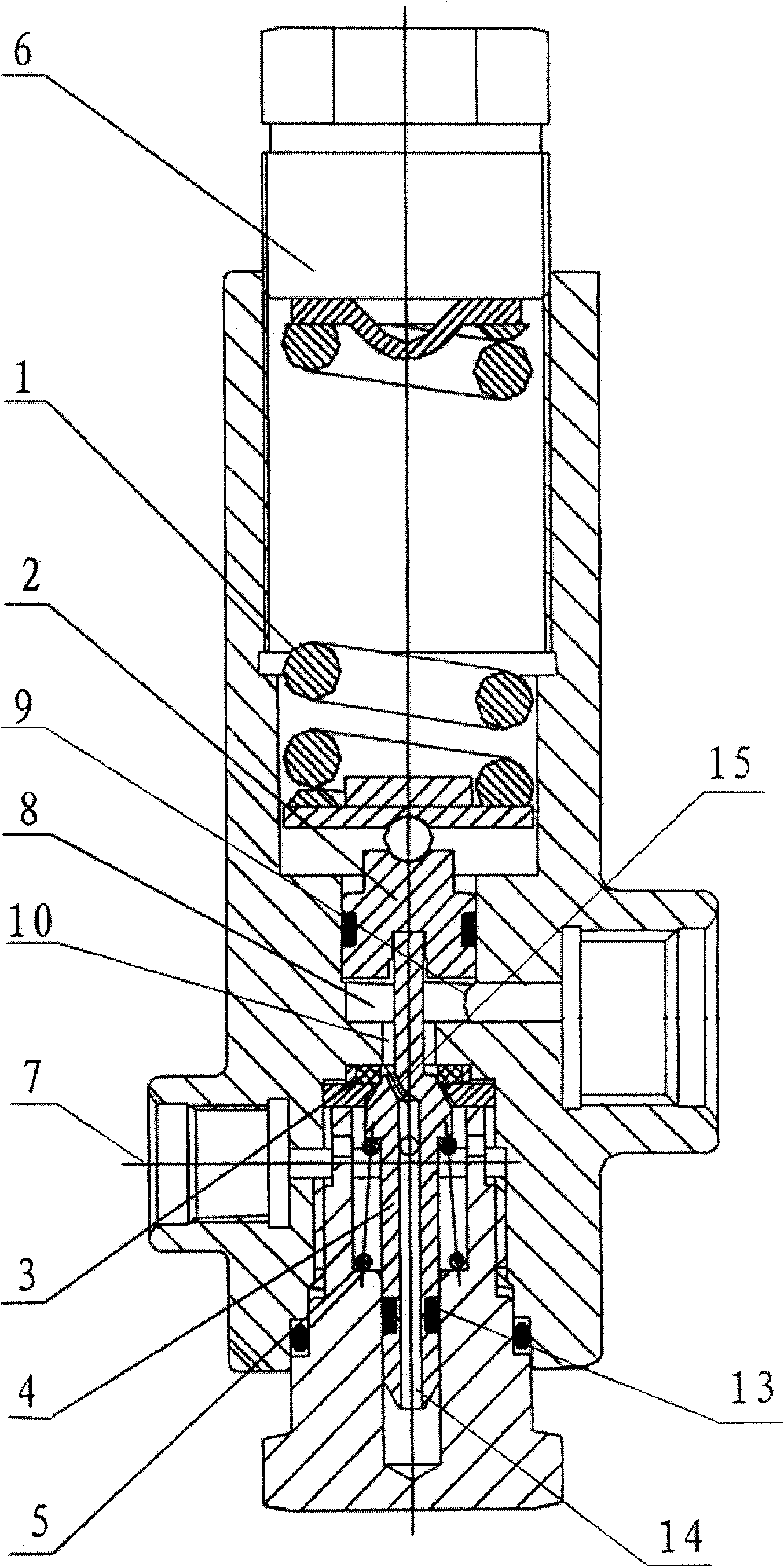
[0013] like figure 1 In the air pressure decompression device shown, a piston cavity is arranged in the housing of the decompression device, and a decompression spring chamber and a ejector rod chamber are connected to the coaxial line at both ends of the piston cavity, and a piston 2 is installed in the piston cavity. The compression spring chamber is equipped with a decompression spring 1 whose inner end is pressure-fitted with the piston 2. The outer end of the decompression spring is press-fitted with a pressure-regulating nut 6 which is helically assembled on the outdoor port of the decompression spring. The top is equipped with a push rod 4 whose inner end is press fit with the piston. The push rod is equipped with a preload spring 5 that drives the push rod to press the piston. The valve seal structure is composed of the dynamic sealing surface and the static seal at the passage 10, the ejector rod chamber is a sealed space, the ejector rod chamber is connected with an ...


PUM


Abstract

The invention relates to an air path relief device. A housing of the relief device is provided with a piston cavity. The two ends of the piston cavity are communicated and provided with a relief spring chamber and a top rod chamber in a same axis. The piston cavity is provided with a piston the inner end of which is in top pressure cooperation with the piston. The external end of the relief spring is in top pressure cooperation with a pressure regulating screw cap spirally arranged in an external port of the relief spring chamber. An inner axis of the top rod chamber is provided with the top rod the inner end of which is in top pressure cooperation with the piston. The top rod is provided with a top pressure spring driving the top rod to support and press the piston. The top rod chamber is communicated with an air inlet. The channel between the piston and the sealing structure is communicated and provided with an air distributing cabin. The sealing of the top rod chamber is realized by a spirally assembled sealing blank cover at the external port of the top rod chamber. A guiding hole of the top rod is arranged on an axis of the sealing blank cover. An external section of the top rod is inserted in the guiding hole. A ring groove is arranged at the circumferential surface of the external section of the top rod. A sealing ring in a sealing cooperation with the guiding hole is arranged in the ring groove. The external section of the top rod is also provided with a channel for communicating the air distributing cabin guiding hole. The channel includes a center blind pore arranged at the external section of the top rod and communicated with the guiding hole and an oblique hole arranged at the middle section of the top rod and for communicating the center blind hole and the air distributing cabin.

Description

technical field [0001] The invention relates to a gas path decompression device and a corresponding gas path decompression device realizing a large decompression ratio. Background technique [0002] At present, known decompressors are mostly made up of preload spring, decompression spring, piston, push rod and sealing surface, gas distribution chamber. The ejector rod and the sealing surface of this kind of pressure reducer are integrated. When the piston is subjected to high air pressure, the piston moves, driving the ejector rod to move, the sealing surface moves away with the ejector rod, the gas passage, the pressure reducer opens, and due to the interception and decompression, The output pressure is lower than the inlet pressure to achieve the decompression effect. The Chinese patent specification with the application number 92222522.2 discloses a two-stage gas pipeline pressure reducing valve, which is composed of a diaphragm type secondary gas pipeline pressure reduc...

Claims


Application Information

Patent Timeline
Patent Type & Authority Patents(China)
IPC IPC(8): F16K17/04G05D16/10
Inventor 石文星张猛
Owner CAMA LUOYANG GAS SUPPLY
Why Eureka
Try Eureka