
Metal V-shaped members and light steel truss connected thereby

A metal and truss technology, applied in truss structures, truss beams, joists, etc., can solve the problem of inconvenient connection between metal V-shaped parts and chords, low local pressure bearing capacity and stable bearing capacity, and reduced components at the joint Bearing capacity and other issues, to achieve the effect of beautiful appearance, large bearing capacity, and improved bearing capacity

Inactive Publication Date: 2008-06-18
北京泰阁泰美家居装饰有限公司 +1
View PDF0 Cites 2 Cited by
  • Summary
  • Abstract
  • Description
  • Claims
  • Application Information

AI Technical Summary

Problems solved by technology

[0007] The purpose of the present invention is to address the deficiencies of the above-mentioned prior art, to provide a light steel truss connected by a metal V-shaped piece and its connection, to solve the problem that the connection between the traditional metal V-shaped piece and the chord is too weak, and the cross-section of cold-formed thin-walled steel The web and flange are prone to premature local buckling and reduce the bearing capacity of the member. The local pressure bearing capacity and stable bearing capacity of the section are low, and the technical problem of small applicable span is solved; and the connection between the metal V-shaped piece and the chord is solved Convenience, construction is too cumbersome and quality cannot be guaranteed, prone to local buckling

Method used


Image

  • Metal V-shaped members and light steel truss connected thereby
  • Metal V-shaped members and light steel truss connected thereby
  • Metal V-shaped members and light steel truss connected thereby

Examples


Embodiment Construction

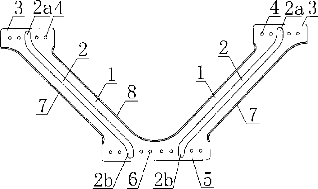
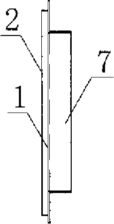
[0033] figure 1 , 2 , 3, and 5 show a typical metal V-shaped embodiment, which is a V-shaped stamped by cold-rolled or hot-rolled thin steel plate or steel strip with a thickness of 0.6-6.0mm (generally 0.8-2.0mm) Integral connectors, the outer edges of the two limb webs 1 have outer flange flanges 7, the inner edges of the two limb webs have inner flange flanges 8, and the cross-sections of the two limb webs are C-shaped; The upper end of the limb forms two upper node planes 3, and the upper node plane 3 has an upper screw hole 4, and the lower ends of the two limbs meet to form a whole lower node plane 5, and the lower node plane 5 has a lower screw hole 6, and the screw hole Various distances should meet the specification requirements. The corners of the upper node plane 3 and the lower node plane 5 form a right angle or an arc angle.

[0034] There are left and right symmetrical indentations in the middle of the abdominal rods of the two limbs, and each limb may have 1-...


PUM


Abstract

The invention provides a V-shaped metal component and a light steel truss connected with the V-shaped metal component, which is an integrated V-shaped connector formed by pressing a steel plate. The outer edges of the web members of the two limbs are provided with outward flanging, while the inner edges of the web members of the two limbs are provided with inward flanging, wherein the top terminals of the outward flanging and the inward flanging extend smoothly to the lateral sides of the upper node plane in an arc shape, the top terminal of the outward flanging extends smoothly to the external side of the lower node plane in an arc shape, and the bottom terminal of the inward flanging extends smoothly in an arc shape and crosses with the bottom terminal of another inward flanging. Two upper node planes are formed at the upper part of the two limbs, wherein the two upper node planes are provided with upper screw holes; the bottom terminals of the two limbs cross with each other to form an integrated lower node plane, wherein the lower node plane is provided with lower screw holes. Symmetrical indentation is arranged between the web members of the two limbs, wherein the terminal of the indentation extends into the upper node plane and the lower node plane of the web members of the two limbs. The V-shaped metal component can be connected with an upper chord and a lower chord via screws to form a light steel truss, and is applicable to the houses with light steel keel structure, and greatly increases the bearing capacity.

Description

(1) Technical field [0001] The invention relates to a metal web connecting piece and a light steel truss connected thereto. (2) Background technology [0002] Light steel keel system houses have the characteristics of small wall thickness, light weight, good seismic performance, fast construction speed, no need for support formwork, and convenient pipeline layout. They have been widely used in my country's construction industry in recent years. In traditional light steel keel system houses, the load-bearing frame of the wall and the roof beams of the floor are generally welded or bolted by a single C-shaped cold-formed thin-walled section steel. The section thickness of the section steel is generally 0.6-2.0mm, and its web The width and thickness of the flange and the flange are relatively large. When the vertical axial compression load is applied, the web and the flange are prone to premature local buckling and reduce the bearing capacity of the member. If it is used as the...

Claims


Application Information

Patent Timeline
Patent Type & Authority Applications(China)
IPC IPC(8): E04C3/04E04C3/02
Inventor 王小平丛玉臣
Owner 北京泰阁泰美家居装饰有限公司
Learn More