
Edge self-adapting de-interlacing interpolation method

An interpolation method and self-adaptive technology, applied in the direction of standard conversion, etc., can solve problems such as interpolation errors and inability to achieve good interpolation effects

Inactive Publication Date: 2008-06-11
ARKMICRO TECH
View PDF0 Cites 21 Cited by
  • Summary
  • Abstract
  • Description
  • Claims
  • Application Information

AI Technical Summary

Problems solved by technology

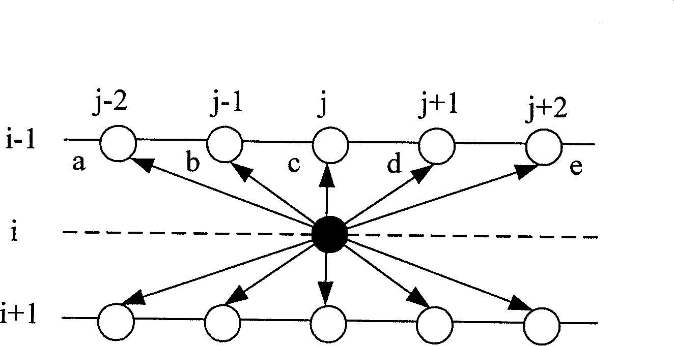
[0009] However, ELA itself also has some weaknesses. For example, it is easy to generate interpolation errors. This is because as the distance between the detected pixel and the center point increases, the difference between pixel pairs tends to become smaller. The above simple 5 directions difference comparison, it is easy to interpolate in the wrong direction
In addition, since only 5 directions are detected, good interpolation effects cannot be obtained for edges in any direction

Method used


Image

  • Edge self-adapting de-interlacing interpolation method
  • Edge self-adapting de-interlacing interpolation method
  • Edge self-adapting de-interlacing interpolation method

Examples


Embodiment Construction

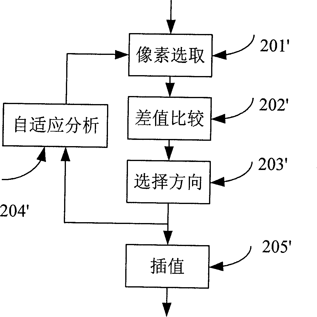
[0055] as attached figure 2 Shown is the overall flowchart of the invention, reflecting four basic steps to realize the present invention:

[0056] Step (201'): select the set of surrounding pixels to be interpolated;

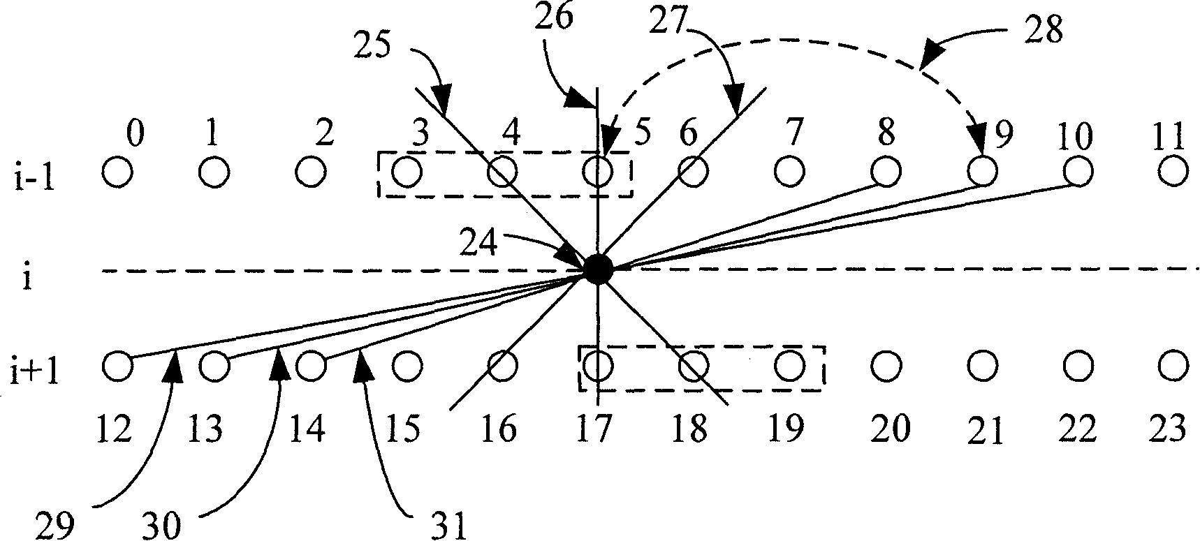
[0057] The three main directions for the point F(i, j) to be inserted are:

[0058] Main northwest direction: the straight line connecting point (i-1, j-1) and point (i+1, j+1);

[0059] Main north direction: the straight line connecting point (i-1, j) and point (i+1, j);

[0060] Main northeast direction: straight line connecting point (i-1, j+1) and point (i+1, j-1);

[0061] The pixel pairs associated with the three main directions are:

[0062] Main northwest pixel pair: ((i-1, j-2), (i+1, j)), ((i-1, j-1), (i+1, j+1)), (( i-1, j), (i+1, j+2));

[0063] Main north pixel pair: ((i-1, j-1), (i+1, j-1)), ((i-1, j), (i+1, j)), ((i- 1, j+1), (i+1, j+1));

[0064] Main northeast pixel pairs: ((i-1, j), (i+1, j-2)), ((i-1, j+1), (i+1, j-1)), (( i-1, j+2)...


PUM


Abstract

The invention discloses an edge adaptive de-interlacing interpolation method which proposes improvements aiming at solving the problems of the prior ELA interpolation method. The interpolation method which adopts an edge adaptive technique and interpolates loss information between two lines by making use of the correlativity of the two lines is characterized in that: the direction with greatest correlativity is selected as an interpolation direction through respective detections on a plurality of directions, and a plurality of groups of data in each direction are further selected for associate judgment, thereby improving the accuracy of the judgment. The method which is a de-interlacing interpolation algorithm with low cost, easy hardware realization, good edge protection and edge saw tooth removal ability can adjust interpolation directions adaptively and bring about good interpolation results in any direction. The method is effective not only two-dimensional interpolation but also for three-dimensional interpolation.

Description

technical field [0001] The present invention relates to a method for improving image resolution when performing deinterlacing processing on digital image signals, in particular to an edge-adaptive deinterlacing interpolation method Background technique [0002] Traditional analog TV images are interlaced, each image frame is divided into two fields, and each field only scans a predetermined number of horizontal lines. In each field period, only half of the horizontal lines in the frame are scanned, and the two fields are displayed sequentially, making the scanning look progressive and allowing the audience to perceive the entire image. The biggest disadvantage of this method is that it will reduce the vertical resolution, because each field only contains half of the vertical information in the complete frame. With the development of digital image technology, more and more high-definition digital TVs appear in people's lives, and they adopt progressive scanning. Therefore, ...

Claims


Application Information

Patent Timeline
Patent Type & Authority Applications(China)
IPC IPC(8): H04N7/01
Inventor 李琛常军锋刘波石岭刘云
Owner ARKMICRO TECH
Learn More