Fixing mechanism of interface card

A fixing mechanism and interface card technology, applied in the direction of support structure installation, digital processing power distribution, etc., can solve the problems of increased manufacturing cost, complex structure, cost increase, etc., and achieve the effects of avoiding loss, reducing manufacturing cost, and simplifying the structure

Inactive Publication Date: 2008-06-11
INVENTEC CORP
View PDF1 Cites 2 Cited by
  • Summary
  • Abstract
  • Description
  • Claims
  • Application Information

AI Technical Summary

Problems solved by technology

[0004] However, the fixing member 14 cooperates with the slot 1041 provided on the fixing plate 104 with a pivot 141 to be pivotally installed in the casing 10, and must be buckled to the second fixing part 142 by the fixing part 142 at the other end of the fixing member 14. The buckle part 121 of a plate body 101 makes the structure of the fixing member 14 and the first plate body 101 complicated and increases the manufacturing cost
[0005] To sum up, how to propose a fixing structure for the interface card, so as to avoid the disadvantages of increasing the cost due to the complicated structure, and avoid the need for hand tools for assembly, has become an urgent technical problem to be solved at present.

Method used


Image

  • Fixing mechanism of interface card
  • Fixing mechanism of interface card
  • Fixing mechanism of interface card

Examples


no. 1 example

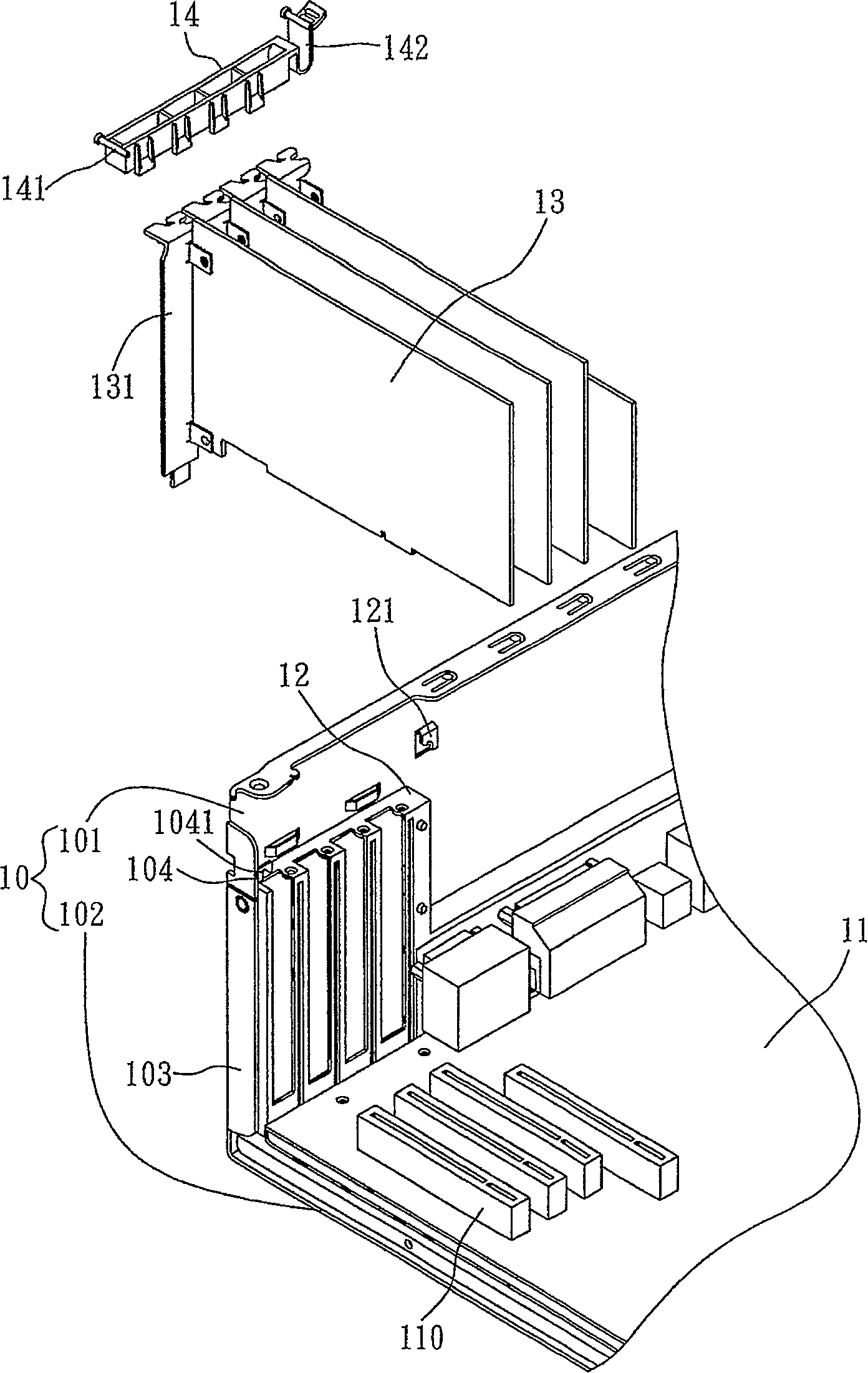
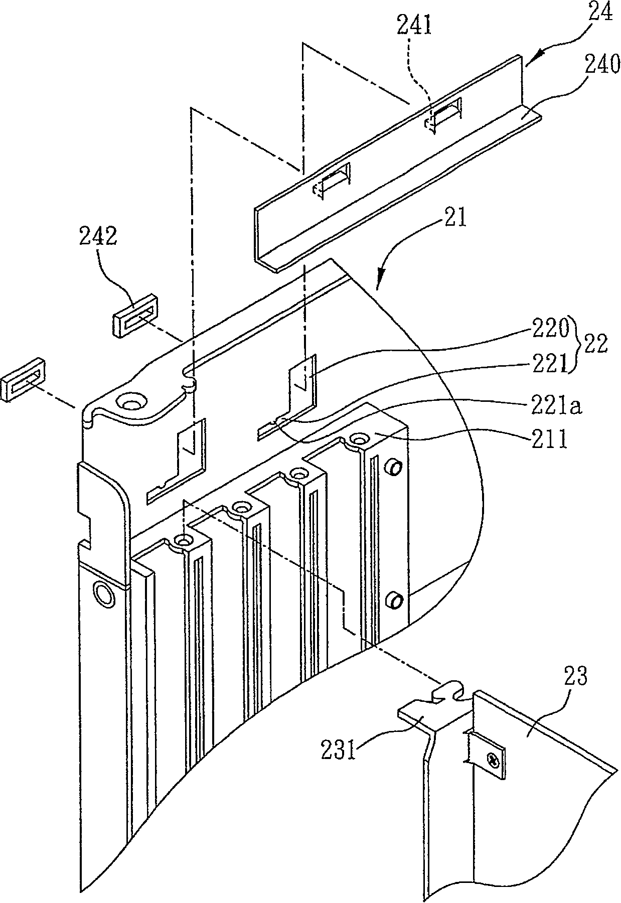
[0052] see Figure 2A to Figure 2CAs shown, it is used to illustrate the first embodiment of the fixing mechanism of the interface card of the present invention, and the described fixing mechanism is for fixing the side plate 231 of at least one interface card 23 to the fixing frame 211 located on the casing 21, Among them, the server case is used as an example to illustrate the applied case 21, and the case 21 is provided with a fixing frame 211 for inserting the side plate 231 of the interface card 23, which is an existing technology and is not a technology of the present invention. feature, in order to make the technical points of the present invention clear and easy to understand, so the insertion relationship between the fixing frame 211 and the side block 231 of the interface card 23 will not be repeated.

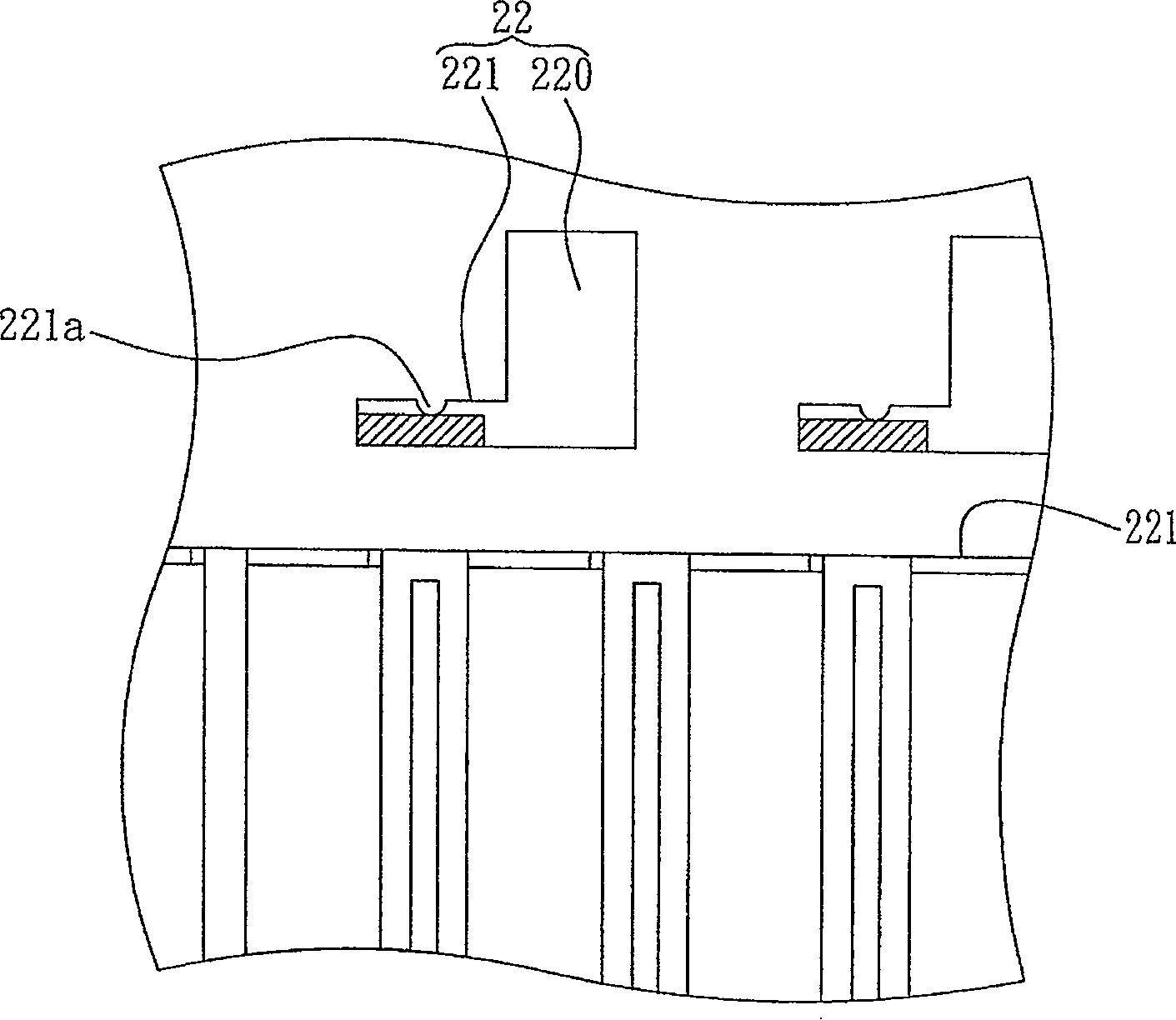
[0053] Such as Figure 2A As shown, the fixing mechanism of the interface card provided by the present invention includes a first guide portion 22 arranged above the...

no. 2 example

[0058] see Figure 3A to Figure 3C As shown, it is used to illustrate the second embodiment of the fixing mechanism of the interface card of the present invention. The difference from the previous embodiment lies in the collocation structure design of the first guide part and the second guide part, and the pressing part Bottom with elastic material.

[0059] Such as Figure 3A As shown, a first guide part 22' having a first end and a second end is provided on the casing 21 relative to the fixing frame 211, and the first guide part 22' is directed from a longitudinal guide groove 220' to The first end and the second end are formed by connecting with a transverse guide groove 221 ′, and an insertion hole 223 ′ with a larger width is formed above the longitudinal guide groove 220 ′. The end of the second guide part 241' of the pressing part 24' has a convex step 241a' relative to the insertion hole 223', so that the convex step 241a' of the guiding protrusion 241' penetrates th...


PUM


Abstract

A fixing structure of an interface card is provided, which is for fixing one side separation strip of an interface card on a fixing frame provided on a shell. The fixing structure comprises a first guidance part with a first end and a second end positioned at the upper part opposite to the fixing frame of the shell, and a pressing piece with a pressing part and a second guidance part, thereby moving to the second end of the first guidance part through the second guidance part to facilitate the pressing part pressing and fixing the side separation strip correspondingly, and moving to the first end through the second guidance part to facilitate the pressing part out of pressing the side separation strip.

Description

technical field [0001] The invention relates to a fixing mechanism for an interface card, in particular to a mechanism for fixing the interface card on a fixing frame applied in a casing. Background technique [0002] The main structure of a computer host is nothing more than a motherboard, a disk drive, and various interface cards, such as a Chinese card, a network card, a sound card, a graphics accelerator card, a display card, etc., to expand the functions of the computer. Placed in the expansion slot of the motherboard, and each interface card is combined with a fixed piece on one side, and each fixed piece is locked to the corresponding expansion slot with screws, so as to avoid the host computer from being slightly bumped or bumped during moving The interface card is loose or falls off, or the expansion slot of the motherboard is damaged due to the loose interface card. However, when each interface card is locked one by one with screws, the fixing screws must be locke...

Claims


Application Information

Patent Timeline
Patent Type & Authority Applications(China)
IPC IPC(8): G06F1/18H05K7/14
Inventor 许玮娟
Owner INVENTEC CORP
Why Eureka
Try Eureka