Reflection display method and device thereof

A technology of reflective display and image display device, which is applied to cathode ray tube indicators, static indicators, optics, etc., can solve the problems of short life, harmful substances in illuminants, and high power consumption of image displays, and achieve energy saving. Effect

Inactive Publication Date: 2008-06-11
KONKA GROUP
View PDF0 Cites 9 Cited by
  • Summary
  • Abstract
  • Description
  • Claims
  • Application Information

AI Technical Summary

Problems solved by technology

[0003] In order to overcome the shortcomings of the prior art, such as large power consumption of the image display, harmful substances contained in the luminous body, relatively short life, and complex system, the present invention proposes a display method that does not require a light source, and provides a method for displaying images using this method. Displayed display device

Method used


Image

  • Reflection display method and device thereof
  • Reflection display method and device thereof
  • Reflection display method and device thereof

Examples


Embodiment Construction

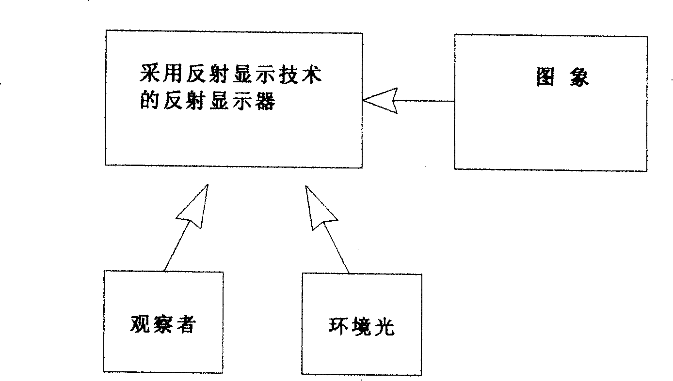
[0026] see Figure 5 , this method is to control and change the reflection characteristics of the display body to ambient light according to the image information to achieve the purpose of displaying the image. It requires a signal processing system, a control system, a controlled light-transmitting body and a reflector to jointly complete the image display, at least including the following step:

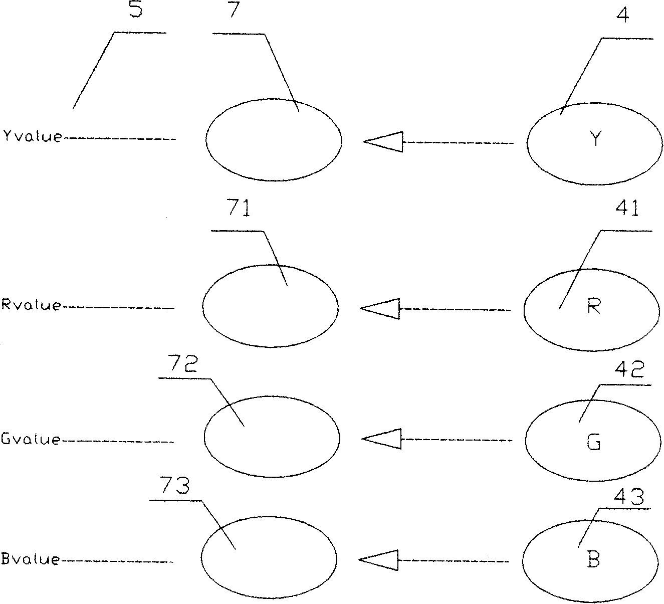
[0027] a. The signal processing system converts the input information into intensity values ​​corresponding to each pixel on the controlled transparent body;

[0028] b. The control system controls each unit corresponding to the controlled transparent body according to the intensity value of each pixel, and adjusts the corresponding light transmittance;

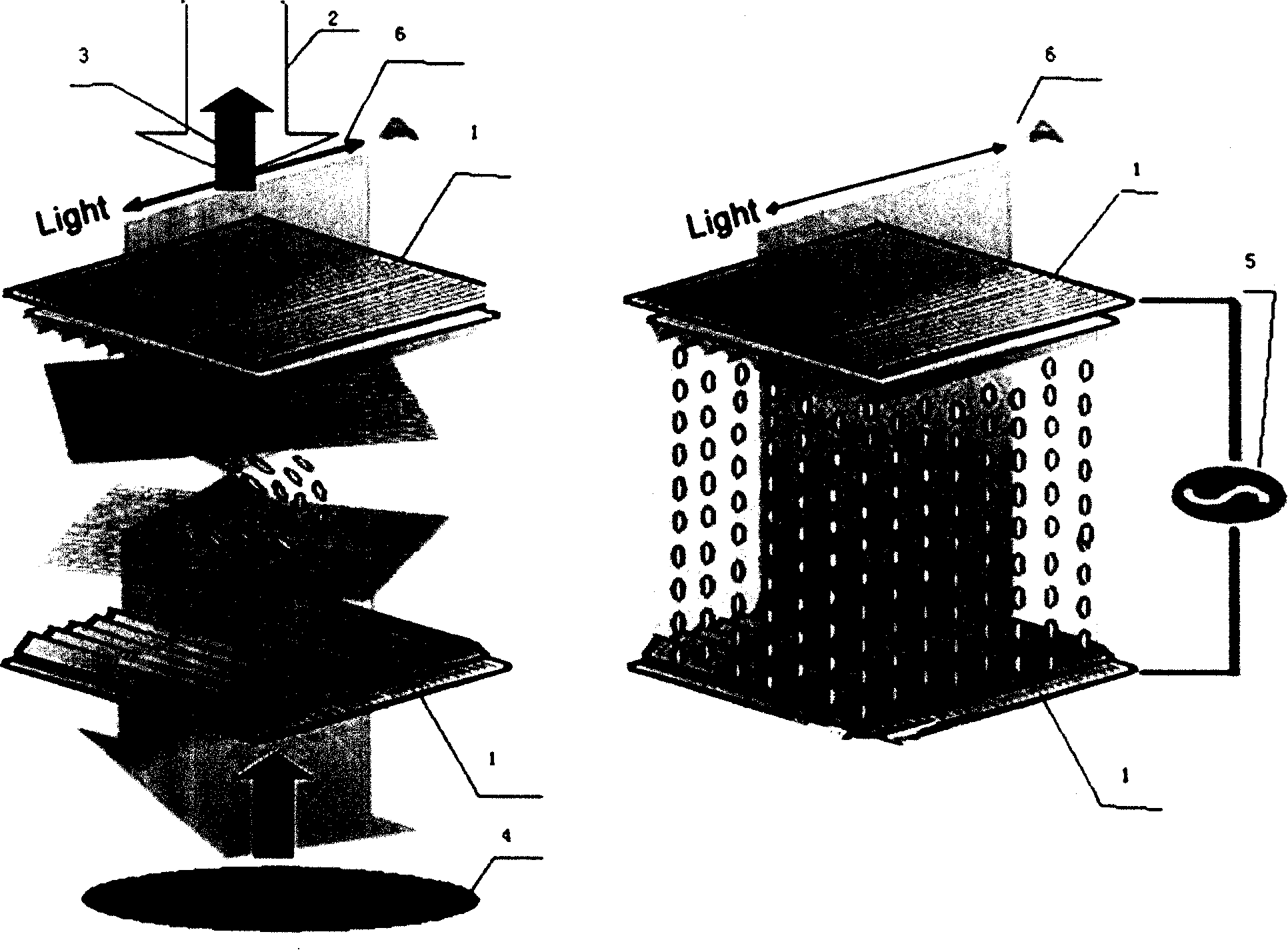
[0029] c. The external light is transmitted according to the transmittance of the corresponding unit of the controlled transparent body set by the control system, and reaches the corresponding unit of the reflector;

[0030] d. T...


PUM


Abstract

A display method by reflection is provided, which is to control and change the reflection characteristic of the display body to the ambient light to realize the image display which requires control system, controlled light transmission body and reflector. A reflective display designed by the method is also disclosed by the invention. Compared with the prior art, the method to reflect display of the invention is to display image by ambient light, which saves the light source needed by display body, energy-saving and environment-friendly. The image watched by the audience is just like to be viewed through glass, natural and real; since no luminous body is required, the invention can be lighter and thinner.

Description

technical field [0001] The invention relates to the field of image display, in particular to a method for controlling and changing the reflection of a display body to ambient light according to image information to display an image and a device for realizing the method. Background technique [0002] In the prior art, image displays mainly include displays that use light-emitting devices to emit light to display images and displays that use passive light-emitting devices to illuminate and display images through backlight. The former is the most common cathode ray tube (CRT) display, which uses image information to control The electron rays emitted by the cathode ray tube collide with the fluorescent screen to emit light and display images. The latter is mainly represented by liquid crystal displays (LCDs), which use passive light-emitting devices, liquid crystals, under the control of image information, to have different light transmission characteristics through the white lig...

Claims


Application Information

Patent Timeline
Patent Type & Authority Applications(China)
IPC IPC(8): G02F1/01G02F1/13G02F1/133G09G3/36G09G5/00
Inventor 何广举
Owner KONKA GROUP
Why Eureka
Try Eureka