
Air cleaner of engine and air cleaner mounting device for mounting air cleaner on engine

A technology of air filter and installation device, which is applied in the direction of fuel air filter, combustion air/combustion-air treatment, engine components, etc., which can solve the problem of increased air filter cover and difficulty in ensuring air filter support Rigidity, low efficiency of fastening work, etc., to achieve the effect of improving the support rigidity

Inactive Publication Date: 2011-01-19
HONDA MOTOR CO LTD
View PDF3 Cites 0 Cited by
  • Summary
  • Abstract
  • Description
  • Claims
  • Application Information

AI Technical Summary

Problems solved by technology

[0011] In addition, in general-purpose engines, the air purified by the air filter is mixed with the fuel in the carburetor supported on the engine, and then the mixed gas is supplied to the engine. The position where the carburetor is away from the engine is supported on the engine in an overhanging state, so there is a problem that it is difficult to ensure the support rigidity of the air filter, and in order to improve the performance of the air filter, the air filter chamber is enlarged In the case of a smaller volume, the air cleaner cover will increase and the above problems will become more significant. Furthermore, in order to fasten the air filter to the engine, sometimes the air filter cover must be removed to install the air filter. Fastened to the engine, which also causes inefficiency in the fastening work of the air filter and the engine

Method used


Image

  • Air cleaner of engine and air cleaner mounting device for mounting air cleaner on engine
  • Air cleaner of engine and air cleaner mounting device for mounting air cleaner on engine
  • Air cleaner of engine and air cleaner mounting device for mounting air cleaner on engine

Examples


no. 1 example

[0091] First, refer to Figures 1 to 11 A first embodiment of the present invention will be described.

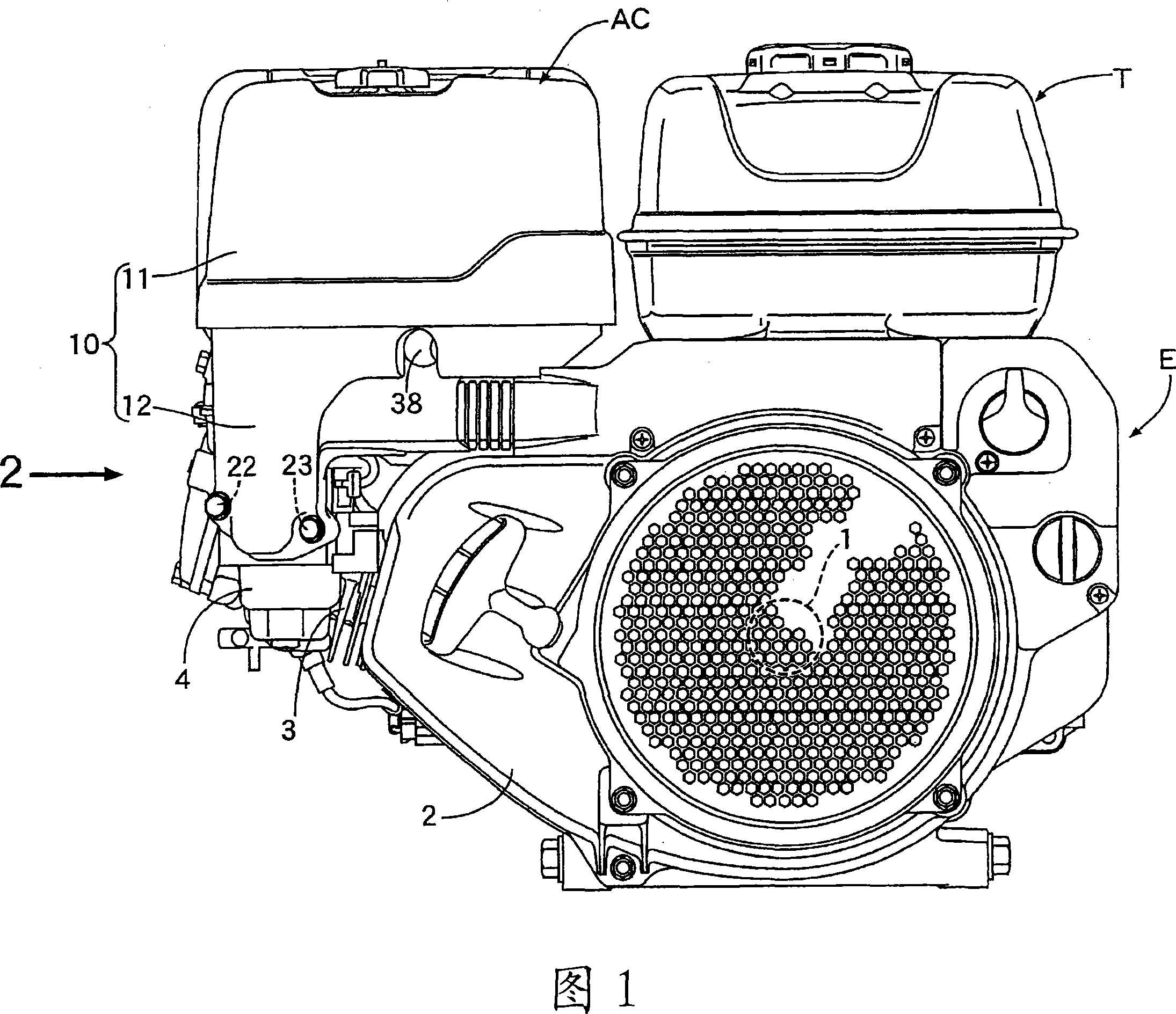
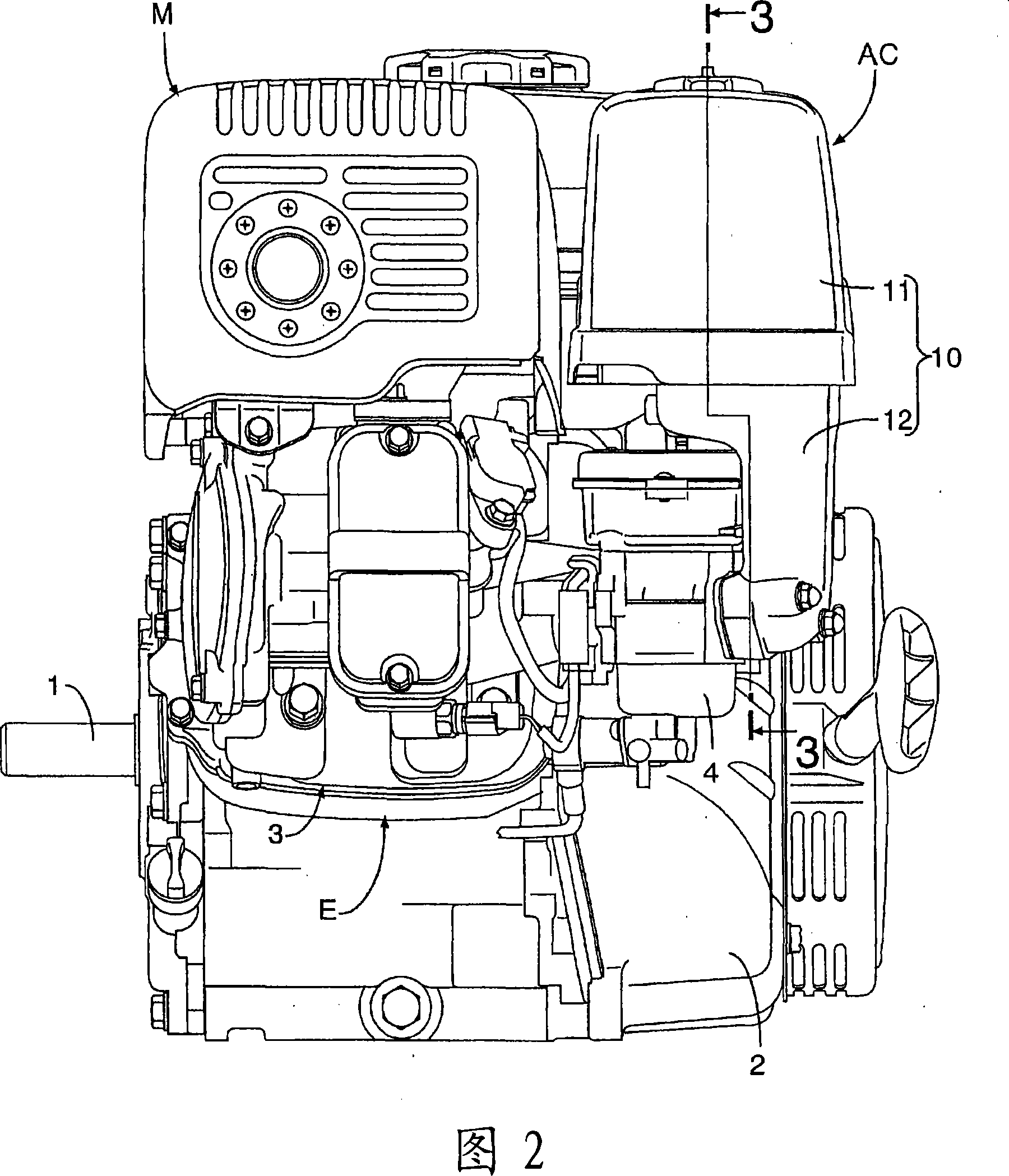
[0092] exist figure 1 , 2 Among them, the general-purpose engine E serving as a power source of various working machines in the general-purpose engine unit is a four-stroke engine, and the general-purpose engine E has a crankcase 2 supporting a crankshaft 1 arranged in the horizontal direction and a crankcase 2 extending obliquely upward from the crankcase 2. The protruding cylinder part 3 is provided with a fuel tank T supported thereon directly above the crankcase 2. In addition, a carburetor 4 is installed on one side of the cylinder part 3. The air filter connected to the carburetor 4 The cleaner AC and the exhaust muffler M connected to the other side of the cylinder unit 3 are arranged on the side of the fuel tank T and directly above the cylinder unit 3 .

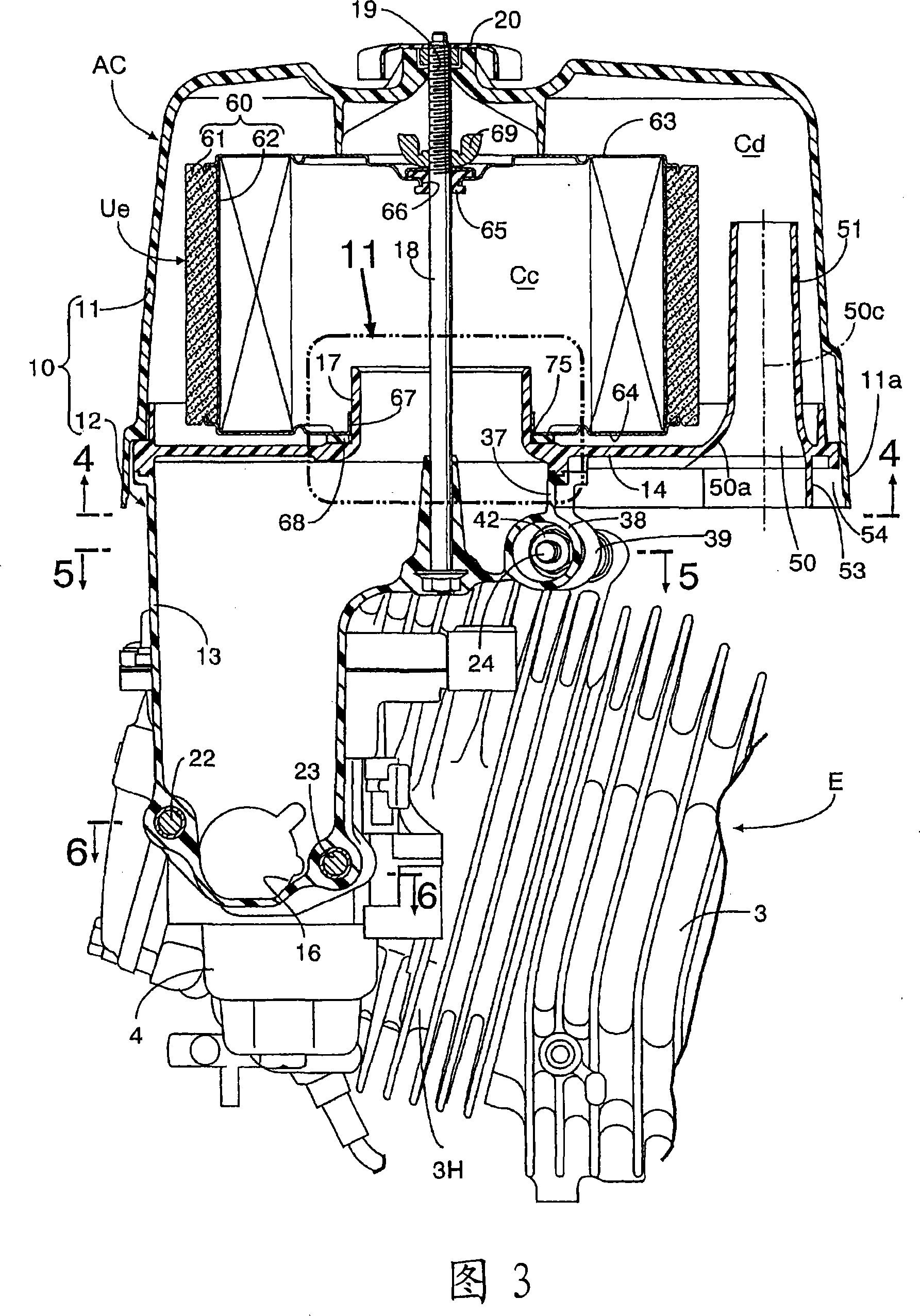
[0093] Refer below Figure 1 to Figure 11 The structure of the air cleaner AC of this invention is demonstr...

no. 2 example

[0118] Refer below Figures 12 to 14 A second embodiment of the present invention will be described.

[0119] This second embodiment is slightly different from the above-mentioned embodiments in the following respects: a sealing gasket made of a rubber gasket is interposed between the upper surface of the partition wall 14 and the lower surface of the lower plate 64 of the filter element unit Ue 268 and the structure of its installation part. The seal packing 268 is formed in a square ring shape, and is fitted on the base outer peripheral surface of the square tube-shaped intake passage 17 in the same manner as in the first embodiment described above. On the middle part of the width direction of the upper sealing surface 271 and the lower sealing surface 273 of the above-mentioned sealing gasket 268, upper and lower lips 272, 274 with a triangular cross section protrude integrally, and the upper lip 272 is in close contact with the filter element unit. Ue is on the lower sur...

no. 3 example

[0123] Refer below Figures 15 to 17 A third embodiment of the present invention will be described.


PUM


Abstract

An air cleaner (AC) of an engine, wherein the skirt wall (11a) of an upper cover body (11) near a suction port (50) is extended to the lower side of the suction port (50) to prevent rain drips flowing down the outer surface of a cleaner cover body (10) from being sucked into the air cleaner through the suction port (50). A seal packing (68) and a cleaner element unit (Ue) are stackingly fitted tothe outer periphery of a suction passage (17) in the cleaner cover body (10), and a locking projection (75) tightly engaged with the suction passage (17) is formed on the seal packing (68) to preventthe seal packing (68) from falling down when the cleaner element unit (Ue) is replaced. Furthermore, the air cleaner (AC) is disposed on one side of the engine (E) parallel with each other, the lowerpart of the cleaner cover body (10) is integrally joined to and supported on the engine (E) together with a carburetor (4) with a pair of connection bolts (22, 23). The reinforcement vertical wall part (37) of the cleaner cover body (10) facing the engine (E) through a clearance is integrally joined to and supported on the engine (E) with the other one connection bolt (24). Thus, the supporting rigidity of the air cleaner for supporting the air cleaner on the engine (E) can be increased.

Description

technical field [0001] The present invention relates to an engine, and in particular to an air cleaner that prevents raindrops flowing down the outer surface of a filter cover provided on a general-purpose engine from being sucked in, and prevents the sucked outside air from being sucked into the engine side without being purified, Furthermore, it relates to an air cleaner installation device for installing an air cleaner on an engine for purifying and introducing the outside air into an engine, especially a general-purpose engine. Background technique [0002] Generally, engine-driven working machines are mostly used outdoors, and since the air filter connected to the intake system of the engine is exposed to the atmosphere, the following disadvantages may be incurred: The raindrops flowing down the outer wall of the body are sucked into the air filter by the intake negative pressure of the engine. [0003] Therefore, it is conventionally known to provide an air cleaner wi...

Claims


Application Information

Patent Timeline
Patent Type & Authority Patents(China)
IPC IPC(8): F02M35/04F02M35/024
Inventor 久保义彦米田新吾坂本一弘松原泰则
Owner HONDA MOTOR CO LTD
Learn More