Relay server, relay communication system and communication device
A technology of communication devices and servers, which is applied in the direction of data exchange and network interconnection through path configuration, and can solve problems such as difficulty
- Summary
- Abstract
- Description
- Claims
- Application Information
AI Technical Summary
Problems solved by technology
Method used
Image

Examples
no. 1 Embodiment approach }
[0070]
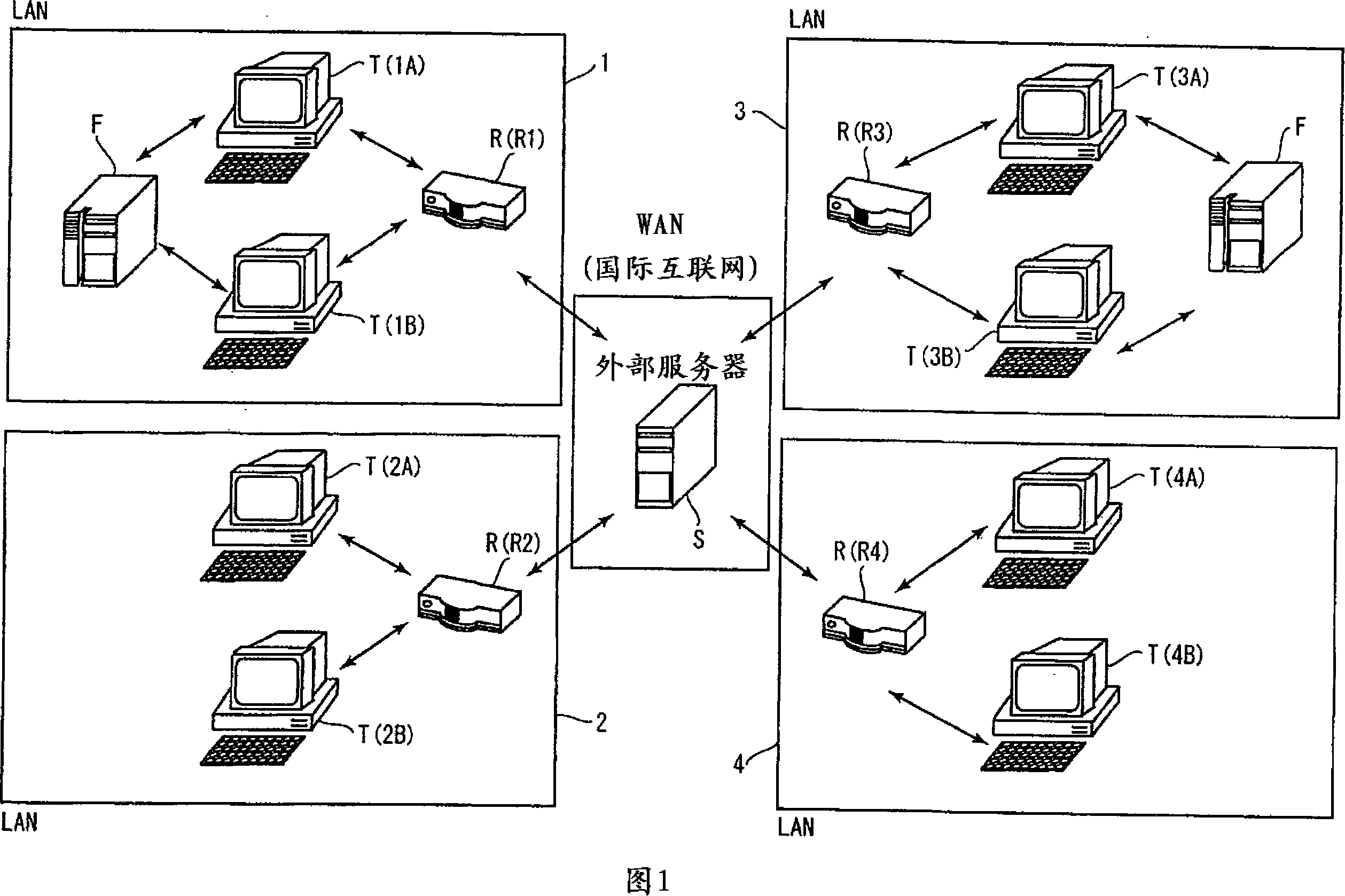
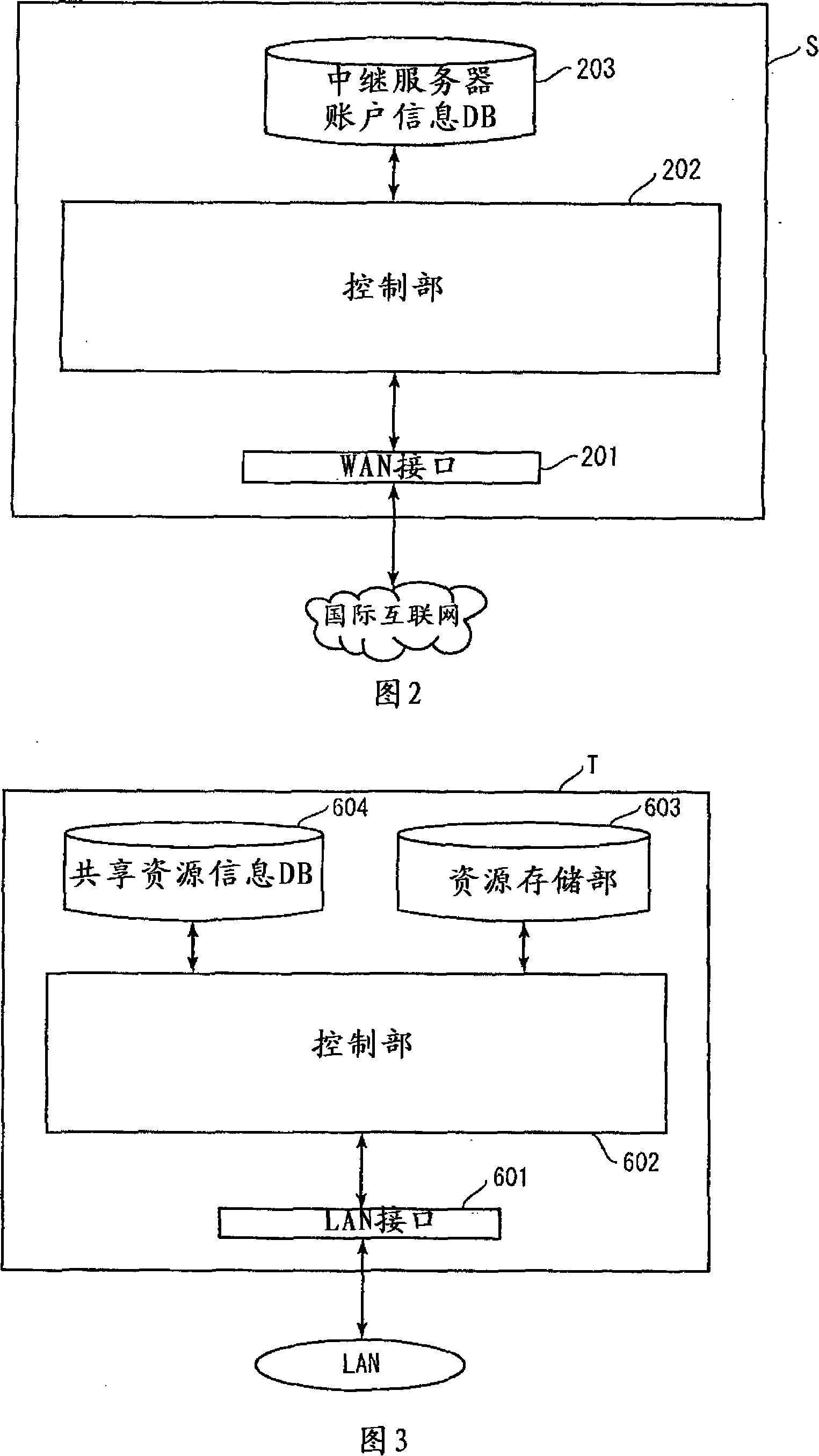
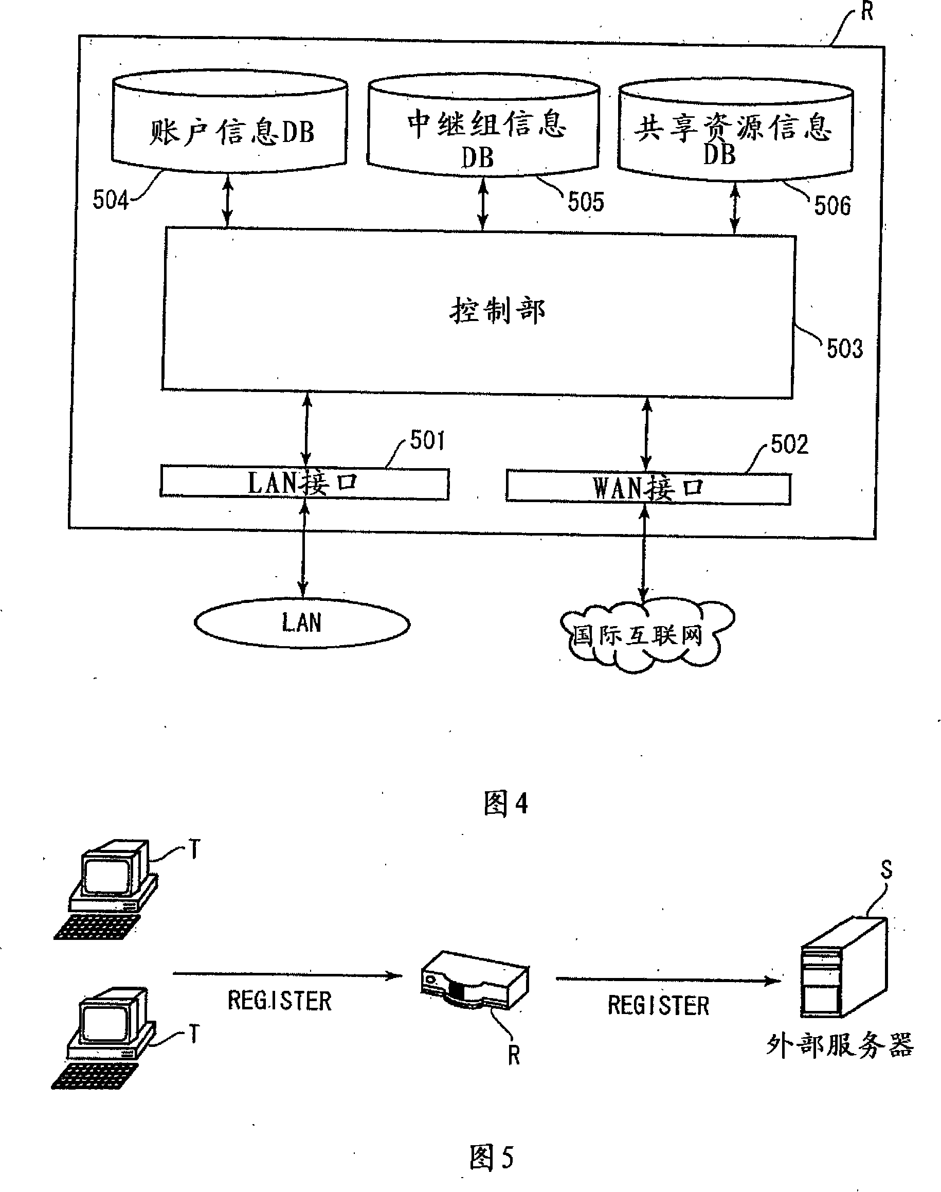
[0071] Next, a first embodiment will be described with reference to the drawings. FIG. 1 is a diagram illustrating an example of the overall configuration of a relay communication system according to the present embodiment. As shown in FIG. 1, this relay communication system is composed of a plurality of LANs connected to a WAN. Furthermore, this relay communication system has an external server S, a relay server R, a client terminal T, a file server F, and the like. In addition, although the embodiment using the external server S was exemplified here, a system in which relay servers R directly communicate without using the external server S may also be used.
[0072]In this embodiment, the communication protocol between the external server S in the WAN and each relay server R, and between the relay server R in the LAN and the client terminal T, etc., is described by way of example. SIP (Session Initiation Protocol: Session Initiation Protocol) system. However, a...
no. 2 Embodiment approach }
[0185]
[0186] Next, a second embodiment will be described. Compared with the first embodiment, this embodiment has the same configuration of the relay communication system, external server S, relay server R, and file server F, but the configuration of the client terminal T is different.
[0187] FIG. 19 shows a functional block diagram of the client terminal T. As shown in FIG. The client terminal T of the present embodiment includes a display unit 605 in addition to the constituent elements of the client terminal T of the first embodiment. The display unit 605 displays the relay group information 100 shown in FIG. 20 and the like, and the shared resource information 120 shown in FIG. 21 and the like.
[0188]
[0189] Next, the processing flow of the client terminal T in this relay communication system will be described with reference to the flow charts in FIG. 22 and FIG. 23 . In addition, the relay group information 100 shown in FIG. 20 and the shared resource infor...
no. 3 Embodiment approach }
[0221]
[0222] Next, a third embodiment will be described. Compared with the second embodiment, this embodiment has the same configuration of the relay communication system, external server S, client terminal T, and file server F, but the configuration of the relay server R is different.
[0223]FIG. 26 shows a functional block diagram of the relay server R. As shown in FIG. The relay server R of the present embodiment has a log information database (DB) 507 in addition to the constituent elements of the relay server R of the second embodiment. The log information DB 507 is a database that manages resource operation content relayed by each relay server R as log information.
[0224]
PUM
 Abstract
Description
Claims
Application Information
 - R&D
- Intellectual Property
- Life Sciences
- Materials
- Tech Scout
- Unparalleled Data Quality
- Higher Quality Content
- 60% Fewer Hallucinations
Browse by: Latest US Patents, China's latest patents, Technical Efficacy Thesaurus, Application Domain, Technology Topic, Popular Technical Reports.
© 2025 PatSnap. All rights reserved.Legal|Privacy policy|Modern Slavery Act Transparency Statement|Sitemap|About US| Contact US: help@patsnap.com