Device for real-time monitoring inside of processor

A technology for internal status and real-time monitoring, applied in hardware monitoring and other directions, can solve the problem that the control point is difficult to cover the chip, and achieve the effect of reliable guarantee

Active Publication Date: 2008-05-28
上海高性能集成电路设计中心
View PDF0 Cites 17 Cited by
  • Summary
  • Abstract
  • Description
  • Claims
  • Application Information

AI Technical Summary

Problems solved by technology

These technologies have played a very important role in the initial debugging of the chip, but as the debugging intensity further increases, it is difficult for the control points added from the original input end of the chip to cover all the functions of the entire chip,

Method used


Image

  • Device for real-time monitoring inside of processor
  • Device for real-time monitoring inside of processor
  • Device for real-time monitoring inside of processor

Examples


Embodiment Construction

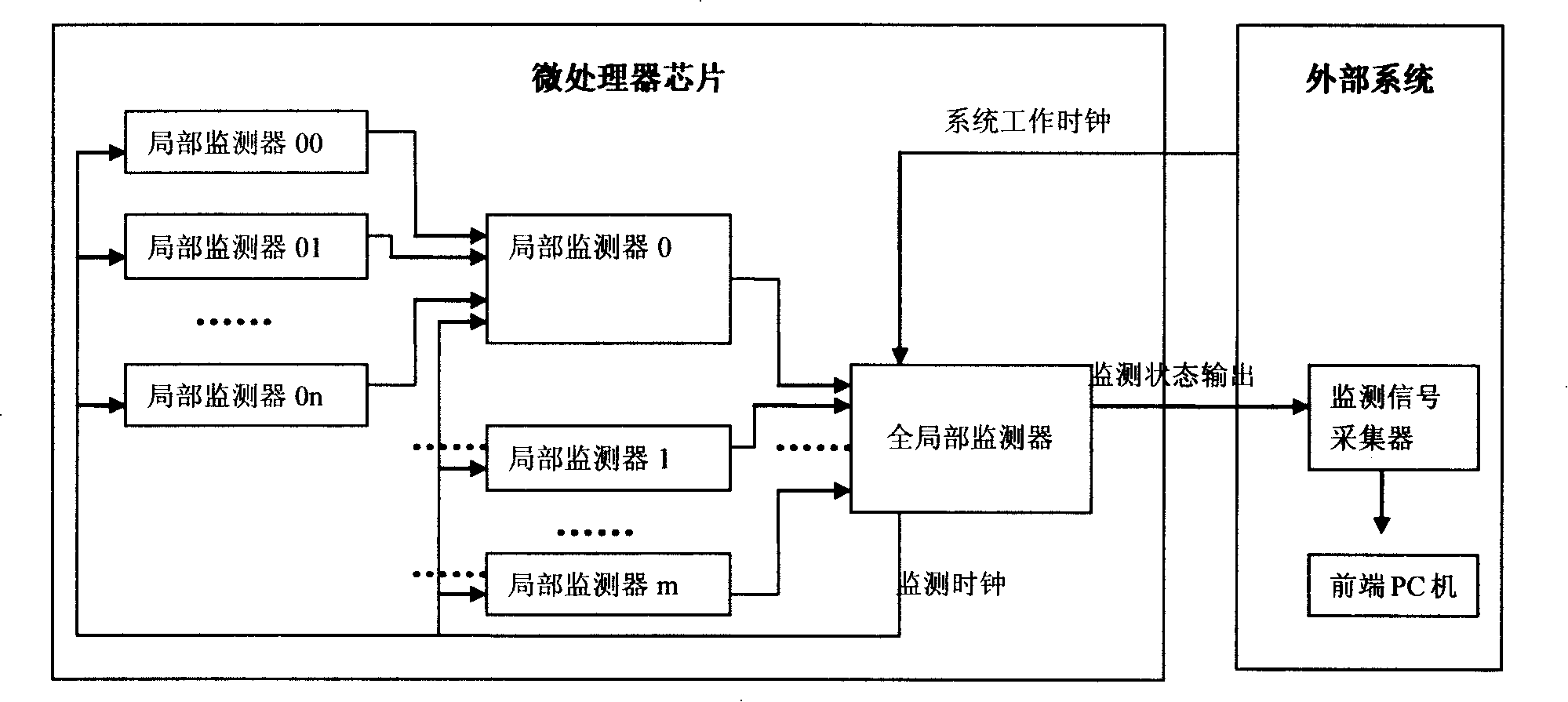
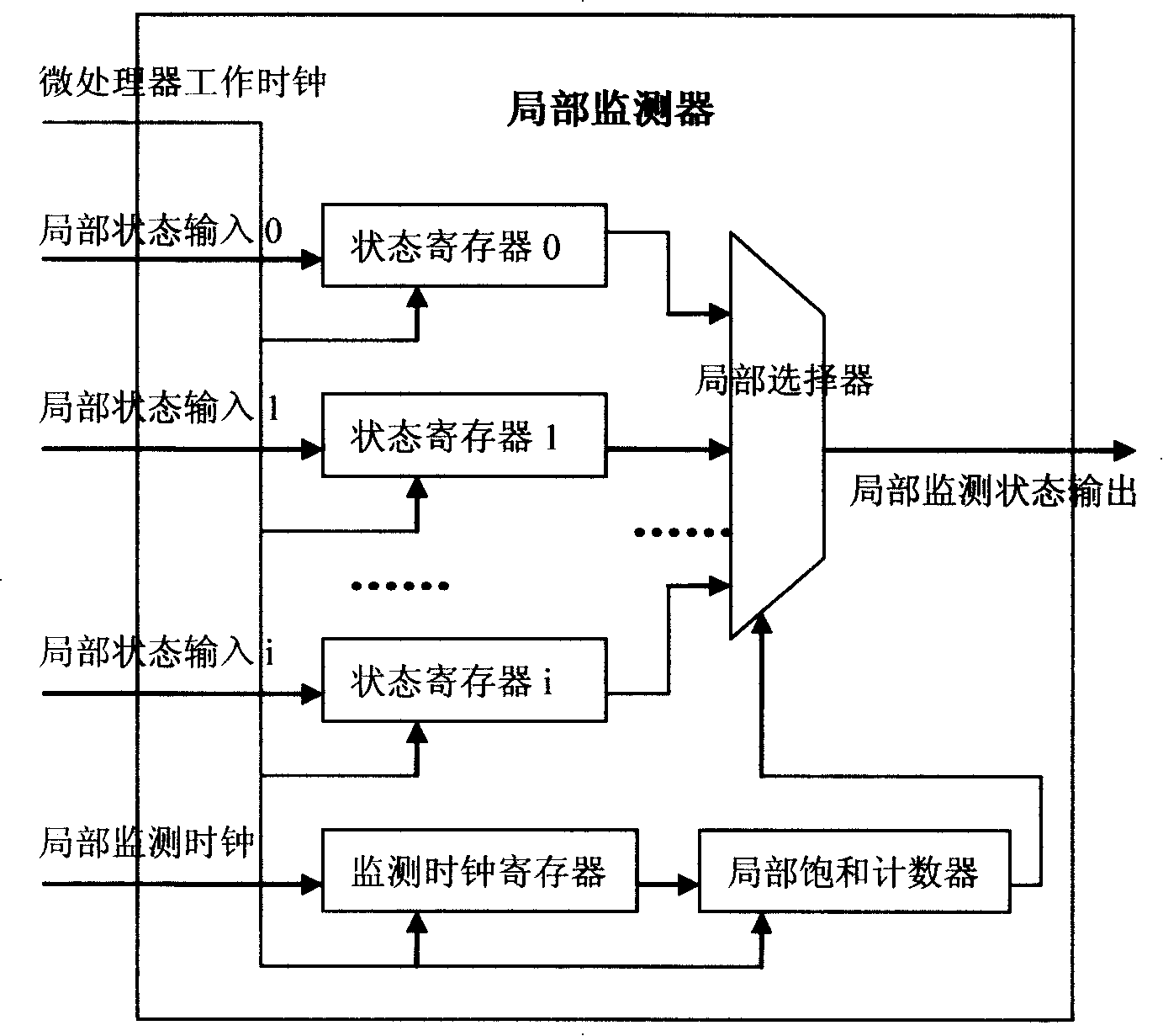
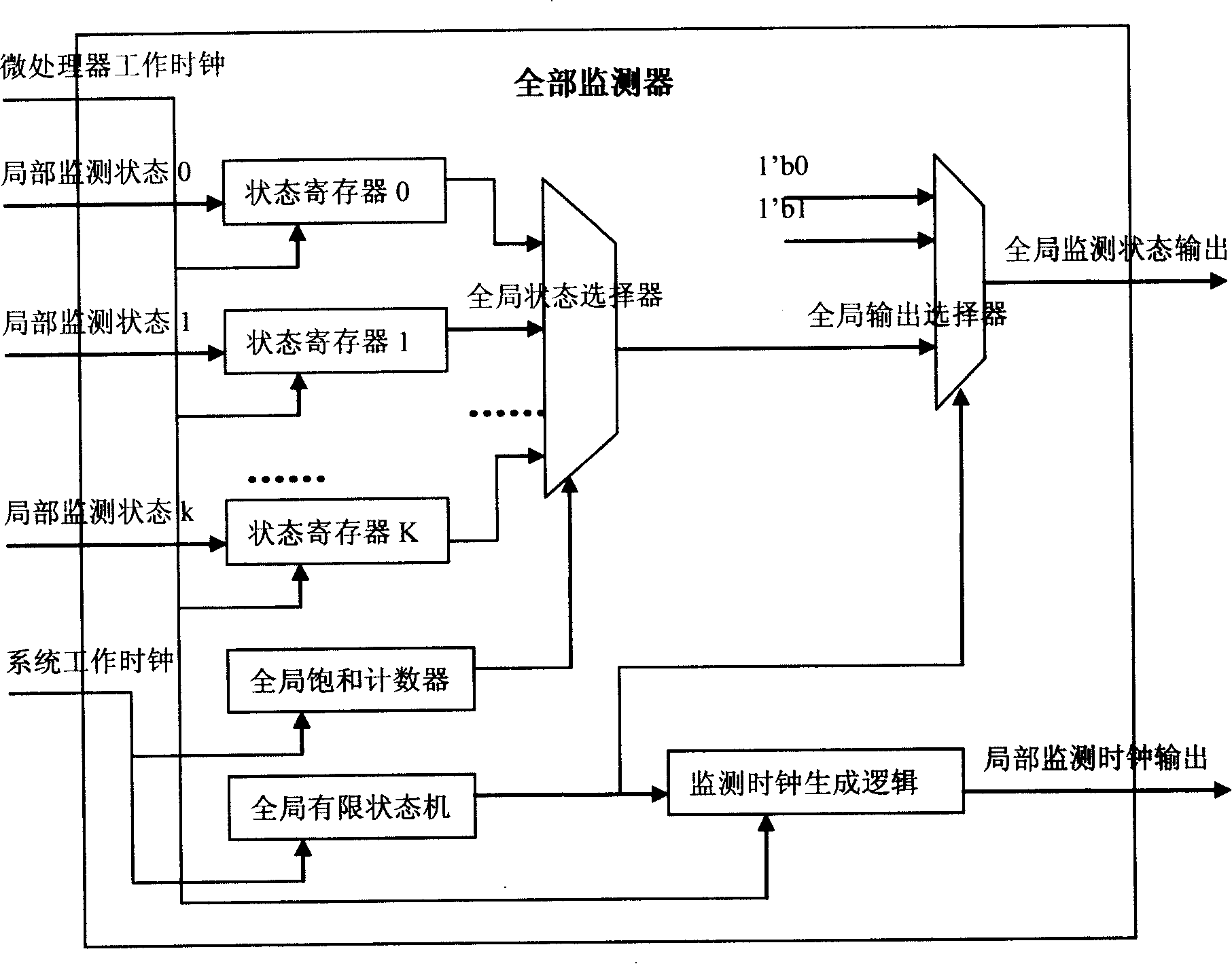
[0013] Such as figure 1 As shown, the device for real-time monitoring of the internal state of the microprocessor of the present invention includes multiple or multi-level local monitors and a global monitor added to the microprocessor, and a monitoring signal collector and a monitor are configured in the external system. Front-end PC. The internal status information of the microprocessor is serially output to the one-bit monitoring status output port in a fixed cycle. The external system is equipped with a monitoring signal collector, and the signal is collected on the monitoring status output port of the microprocessor and passed through the shift register , Spliced ​​into actual processor internal state information, and finally displayed on the front-end PC.

[0014] The status information that needs to be monitored is the output of a series of flip-flops inside the processor, which are distributed in different physical locations in the chip. In order to reduce the connection ...


PUM


Abstract

The invention discloses a device for detecting inner state of a micro processor in real time. During the design process of the micro processor, a plurality of partial monitors or a multi-level partial monitor and a global monitor are added, and the inner state information of the micro processor is serially output to a one-bit state-monitor output port with fixed cycle in circulating manner. The outer system is allocated with a signal-monitor collecting device which collects signal in the state-monitor output port of the micro processor, and is split-jointed into inner state information of the micro processor which has practical meanings through a shift memory, and is displayed on a front end PC machine finally. Small amount of hardware cost added in the design stage of the micro processor, real-time observability of the inner state of the micro processor under the situation of practical running mode of a chip is supported, and the shortcoming of measurable design technology of a traditional chip is compensated.

Description

Technical field [0001] The invention relates to a device for real-time monitoring of the internal state of a processor. Background technique [0002] With the continuous development of microprocessor technology and microelectronic processing technology, the scale and complexity of microprocessor chips (the chips mentioned below refer to microprocessor chips) continue to increase, which greatly increases the chip test time; although the chip packaging The number of pins has increased, but the number of pins used for external testing has been relatively reduced, and the difficulty of testing the internal logic of the chip has continued to increase; in addition, expensive test equipment makes the test cost increase exponentially with the complexity of the chip. For this reason, people have gradually realized the importance of the design-for-test (DFT: Design-For-Test) idea, that is, the mode of combining logic design and test design is adopted, and the designer will consider testabi...

Claims


Application Information

Patent Timeline
IPC IPC(8): G06F11/32
Inventor 胡向东董建萍
Owner 上海高性能集成电路设计中心
Why Eureka
Try Eureka