Gear mechanism for a heald shaft drive
What is Al technical title?
Al technical title is built by PatSnap Al team. It summarizes the technical point description of the patent document.
A gear mechanism and gear technology, applied to belts/chains/gears, looms, heddles, etc., can solve problems such as different loads of two planetary gears
Inactive Publication Date: 2012-07-04
GROZ BECKERT KG
View PDF1 Cites 0 Cited by
Summary
Abstract
Description
Claims
Application Information
AI Technical Summary
This helps you quickly interpret patents by identifying the three key elements:
Problems solved by technology
Method used
Benefits of technology
Problems solved by technology
[0004] In this gear mechanism, different loads on the two planetary gears may result
Method used
Image
Click on the blue label to locate the original text in one second.
Reading with bidirectional positioning of images and text.
Examples
Embodiment Construction
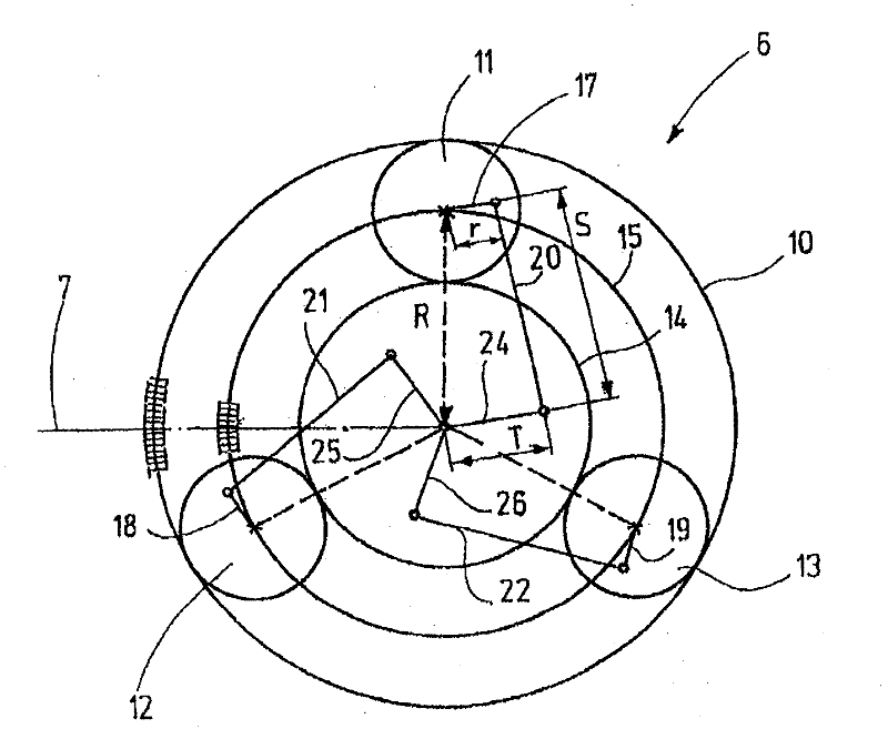
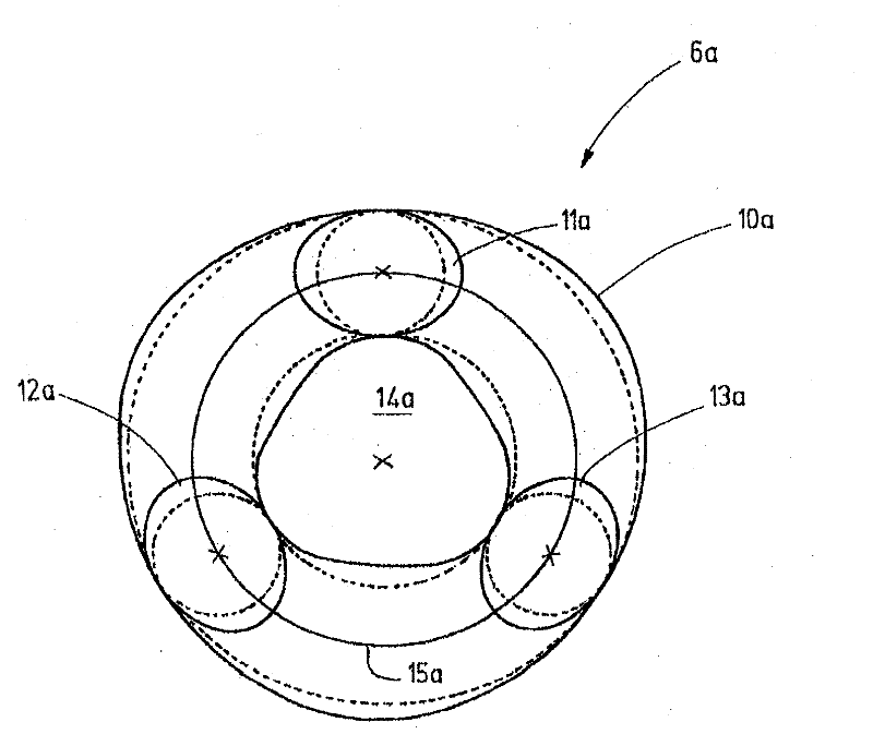
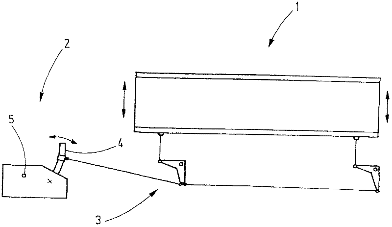
[0065] exist figure 1The corresponding shaft drive 2 of the heald frame 1 is shown in , which causes the vertical movement of the heald frame 1 via the connecting rod 3 as indicated by the two arrows. The shaft drive 2 has a rocker arm 4 that can perform a reciprocating swinging motion. This movement comes from the rotation of the shaft 5 via, for example, an eccentric gear mechanism. If this rotation is a constant accelerated or decelerated rotary motion, then the motion of the heald frame 1 should essentially correspond to a sinusoidal motion. In this case, the sinusoidal form of the deviation, which drives the rocker arm 4 via the connecting rod 3 and the connecting rod, can be ignored. In the shaft drive according to the invention, however, the movement of the shaft 5 is not a constant rotational movement. As an alternative, functioning as a reduction gear, according to figure 2 The gear mechanism 6 produces a rotational movement on an output shaft coincident with the...
PUM
Abstract
The present invention relates to a gear mechanism for the drive assembly of a heald shaft ( 1 ), wherein the gear mechanism ( 6, 6 a, 6 b, 6 c) comprises an input shaft ( 7, 7 b, 7 c) and an output shaft ( 5, 5 b, 5 c). The gear mechanism ( 6, 6 a, 6 b, 6 c) generates a differential angle of rotation between the input shaft ( 7, 7 b, 7 c) and the output shaft ( 5, 5 b, 5 c) that is superimposed on the angle of rotation and, in dependence on the angle of rotation, is subjected to an oscillating change. This oscillating change can differ from a harmonic oscillation as a result of the non-circular design of the planet gears ( 11 a, 12 a, 13 a) of the gear mechanism ( 6, 6 b, 6 c), thereby making it possible to realize almost any optional movements for the heald shaft ( 1 ), with low strain on the gears and the bearings. The invention furthermore discloses a simple production method and a compact design.
Description
technical field [0001] The invention relates to gear mechanisms for heald frame drives. Background technique [0002] Weaving machines have so-called heald frames, which are formed from substantially square frames, which carry a large number of healds. The heald guides the warp thread (Kettfaden) in a targeted manner so that it moves out of the warp thread plane to form the shed (Webfach). For this, the heald frame must move up and down according to a specific setting. For this reason, it is necessary to use a so-called shaft transmission mechanism for driving, which produces an oscillating reciprocating motion when it is driven. This movement is transmitted to the heald frame via the connecting rod. The oscillating reciprocating motion of such a power take-off is usually derived from the constant rotational motion of the drive shaft. If, for example, an eccentric gear mechanism is used, then there is a predetermined relationship between the rotational movement of the in...
Claims
Application Information
Patent Timeline
Application Date:The date an application was filed.
Publication Date:The date a patent or application was officially published.
First Publication Date:The earliest publication date of a patent with the same application number.
Issue Date:Publication date of the patent grant document.
PCT Entry Date:The Entry date of PCT National Phase.
Estimated Expiry Date:The statutory expiry date of a patent right according to the Patent Law, and it is the longest term of protection that the patent right can achieve without the termination of the patent right due to other reasons(Term extension factor has been taken into account ).
Invalid Date:Actual expiry date is based on effective date or publication date of legal transaction data of invalid patent.