Liquid-jet apparatus
A spray device and liquid technology, applied in printing and other directions, can solve problems such as ink waste
- Summary
- Abstract
- Description
- Claims
- Application Information
AI Technical Summary
Problems solved by technology
Method used
Image

Examples
Embodiment approach 1
[0043] Hereinafter, the best mode for carrying out the present invention will be described with reference to the drawings. In addition, in the embodiments described below, various limitations are made as preferred specific examples of the present invention, but the scope of the present invention is not limited to these unless there is no description of the meaning of limiting the present invention in the following description. Way. In addition, in this embodiment, an ink jet recording device (hereinafter, a printer) which is a typical liquid ejecting device will be described as an example.
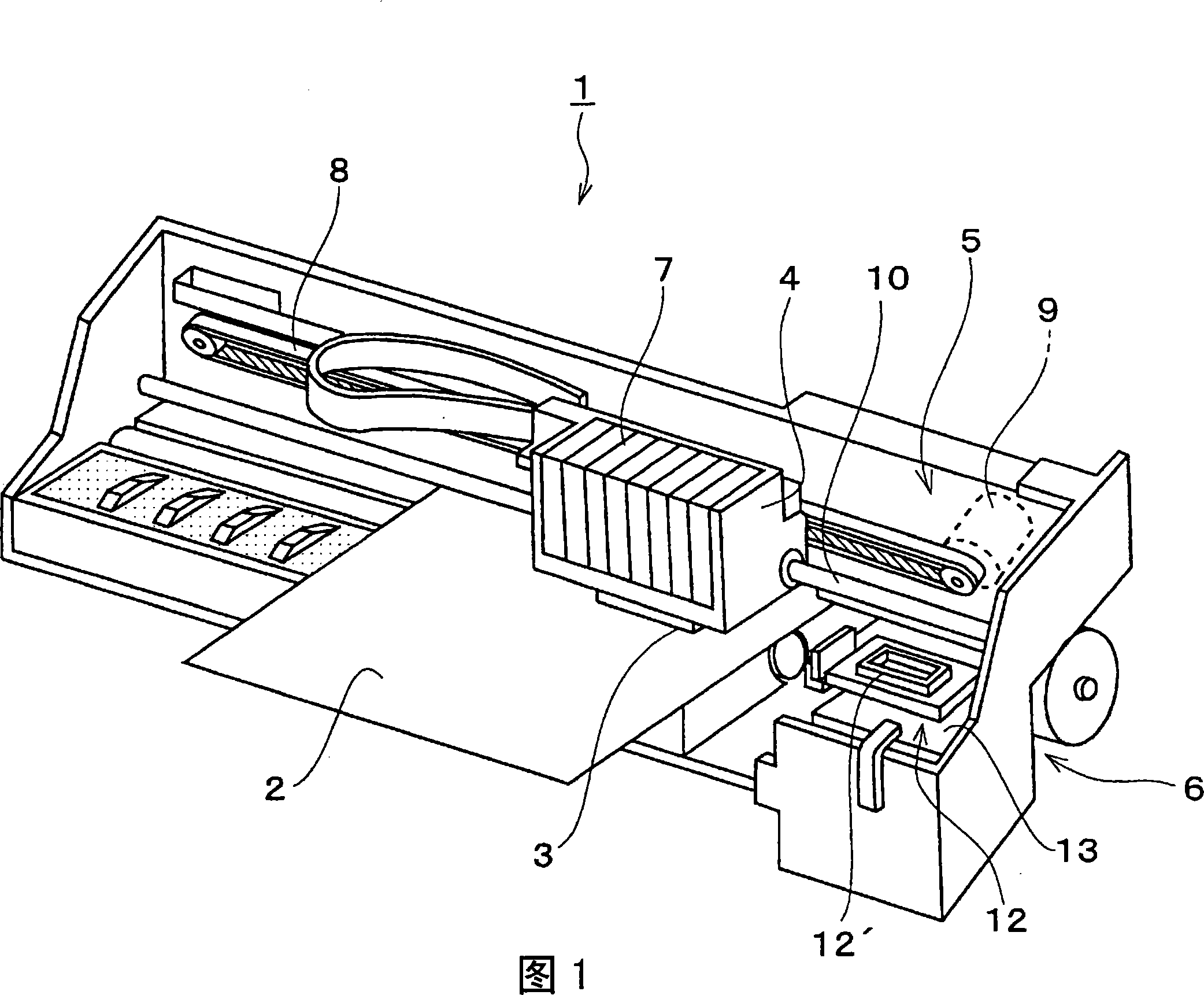
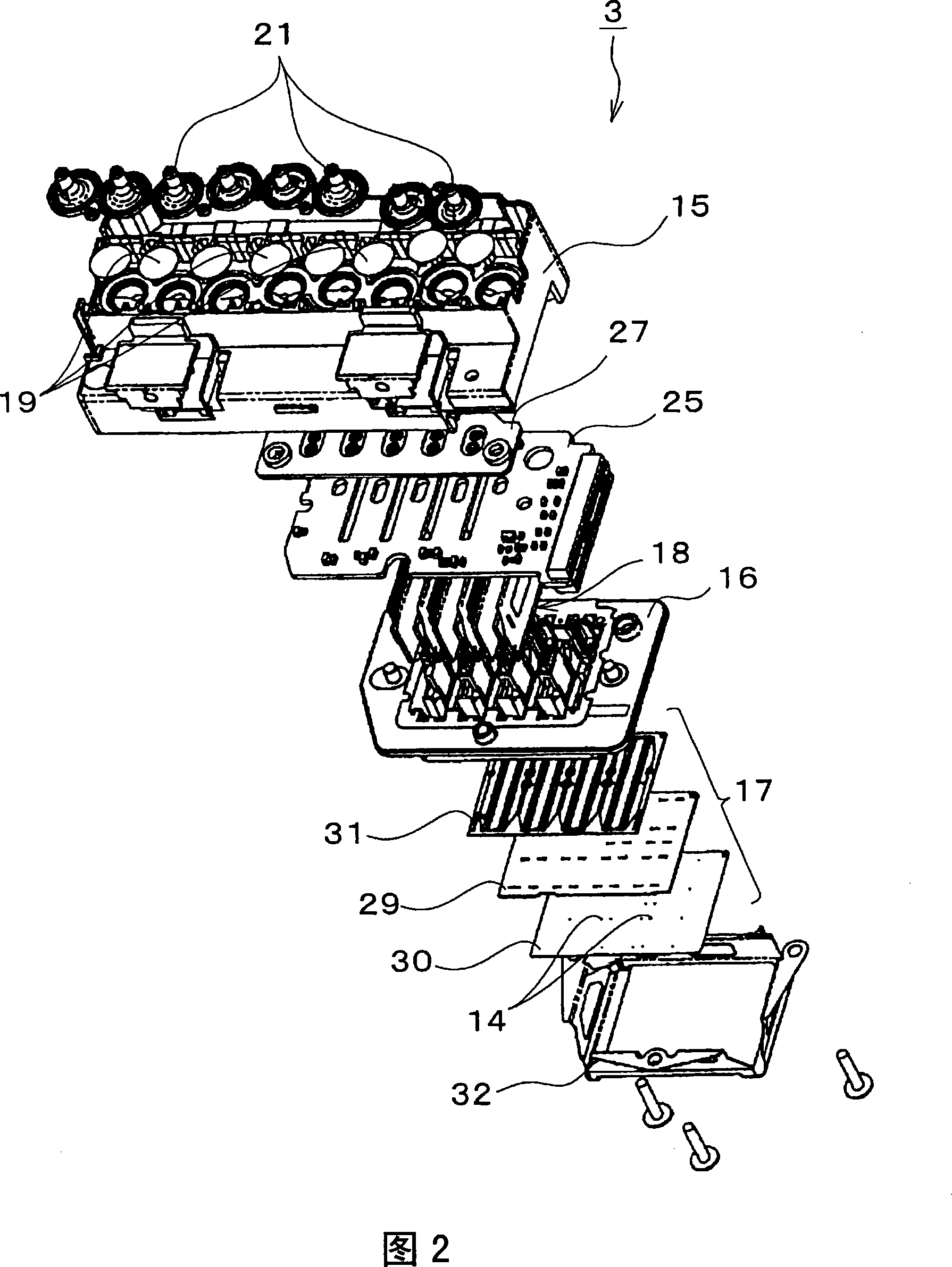
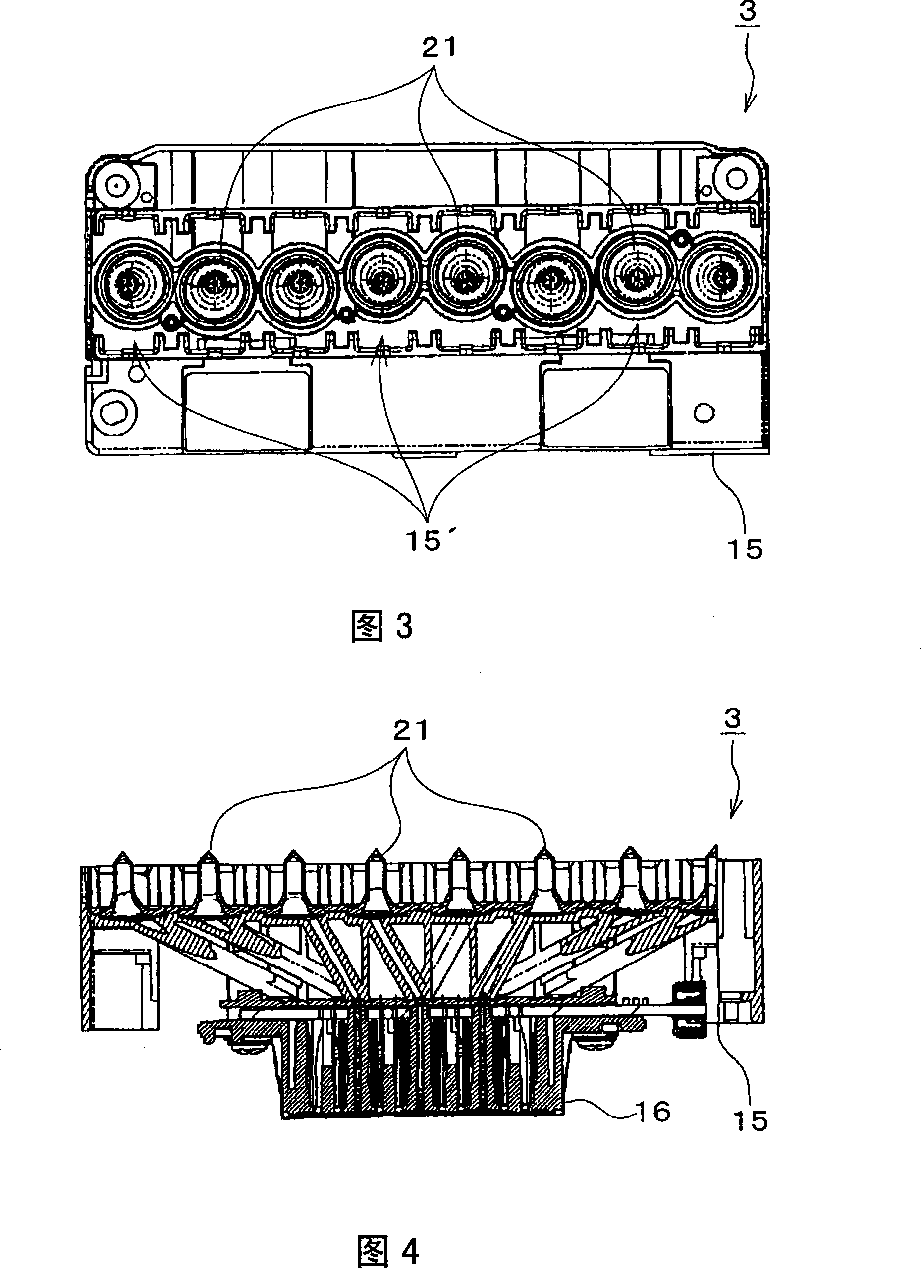
[0044] Here, FIG. 1 is a perspective view of a printer represented by an inkjet recording device, FIG. 2 is an exploded perspective view of a recording head, FIG. 3 is a plan view of the recording head, FIG. 4 is a cross-sectional view of the recording head, and FIG. 5 is an outline of the recording head. Sectional view.
[0045] First, with reference to FIG. 1 , a schematic configuratio...
Embodiment approach 2
[0074] In Embodiment 1, the ink introduction needle 21 is provided with the groove portion 54 to discharge the air in the needle insertion port 44 to the outside, but by providing the groove portion corresponding to the sealing film 46 sealing the needle insertion port 44, more reliable The air in the needle insertion port 44 is exhausted to the outside. Hereinafter, the ink introduction needle of this embodiment will be described. In addition, the same code|symbol is attached|subjected to the same part as Embodiment 1, and redundant description is abbreviate|omitted.
[0075] First, the ink cartridge 7A will be described. FIG. 11 is a sectional view of a needle insertion port portion of the ink cartridge, and FIG. 12 is a perspective view of a valve body of the ink cartridge.
[0076] The ink cartridge 7A functions as a type of liquid storage means of the present invention, and stores ink supplied to the recording head 3 . The printer 1 of the present embodiment can eject ...
Embodiment approach 3
[0104] In Embodiment 1 and Embodiment 2, ink introduction needles 21 , 21A, 21B having tapered tips as liquid introduction columnar bodies were described, but the shape is not limited to this. The liquid introduction columnar body may be shaped to break the seal film 46 of the ink cartridge 7, 7A and insert it into the needle insertion port 44 to introduce the ink in the ink cartridge 7, 7A to the ink introduction path 38. For example, a protrusion protruding toward the needle insertion opening 44A of the ink cartridge 7, 7A may be provided. Fig. 19 (a) is a top view of the needle insertion port of the ink cartridge, Fig. 19 (b) is a top view of the ink introduction needle, Fig. 19 (c) is a cross-sectional view taken along line XX of Fig. 19 (b), and Fig. 19 (d) is a top view of the ink cartridge. (b) YY line sectional view. Hereinafter, the same parts as those of the inkjet recording apparatuses of Embodiments 1 and 2 are denoted by the same reference numerals, and redundant...
PUM
 Abstract
Description
Claims
Application Information
 - R&D
- Intellectual Property
- Life Sciences
- Materials
- Tech Scout
- Unparalleled Data Quality
- Higher Quality Content
- 60% Fewer Hallucinations
Browse by: Latest US Patents, China's latest patents, Technical Efficacy Thesaurus, Application Domain, Technology Topic, Popular Technical Reports.
© 2025 PatSnap. All rights reserved.Legal|Privacy policy|Modern Slavery Act Transparency Statement|Sitemap|About US| Contact US: help@patsnap.com