
Device for air-cooling electronic apparatus

An electronic equipment, air cooling technology, applied in the construction of electrical equipment components, cooling/ventilation/heating transformation, electrical components, etc., can solve the disadvantages of space saving and manufacturing cost, excluding special devices for dustproof performance and cooling capacity, etc. problem, achieve the effect of preventing dust accumulation and improving performance

Active Publication Date: 2008-05-21
JVC KENWOOD CORP
View PDF1 Cites 7 Cited by
  • Summary
  • Abstract
  • Description
  • Claims
  • Application Information

AI Technical Summary

Problems solved by technology

In both cases, however, the device is disadvantageous in terms of saving space and manufacturing costs
[0012] For example, the heat release structure for equipment described in paragraphs [0013] to [0027] of Japanese Patent Application Laid-Open No. 2002-353677 and shown in FIGS. Whether the structure is in a horizontal or vertical position, but it does not include special devices for improved dust protection and cooling

Method used


Image

  • Device for air-cooling electronic apparatus
  • Device for air-cooling electronic apparatus
  • Device for air-cooling electronic apparatus

Examples


Embodiment Construction

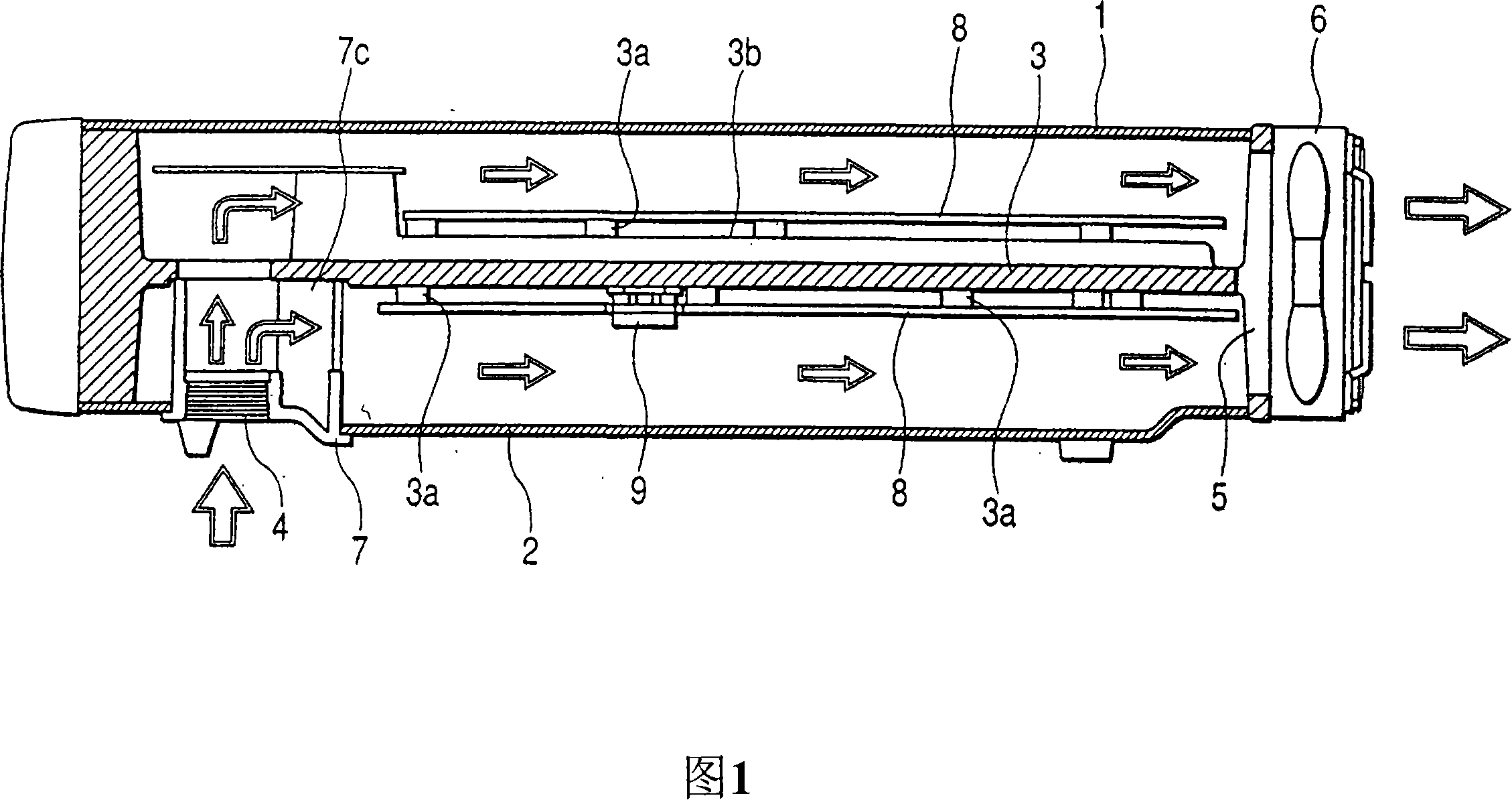
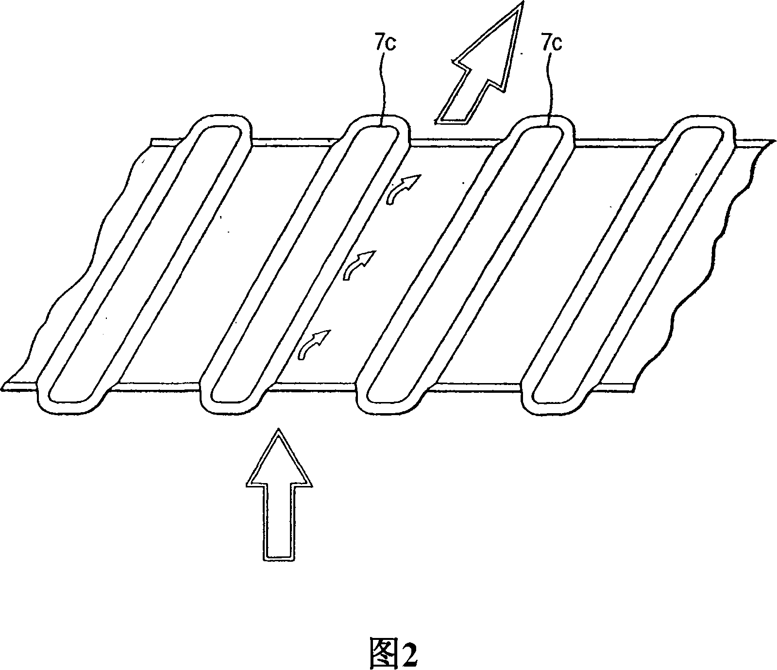
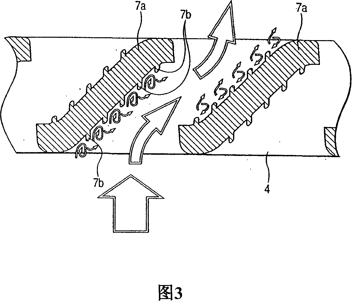
[0036] Preferred embodiments for carrying out the present invention will be described below with reference to Examples. FIG. 1 is a cross-sectional view illustrating an apparatus for air cooling electronic equipment according to an embodiment of the present invention. The upper case 1 and the lower case 2 shown in FIG. 1 are connected to sandwich a bottom plate 3 and constitute a case for accommodating electronic equipment. Suction openings 4, 4 shown in FIG. In addition, the fan 6 is fixed on the bottom plate 3 .

[0037] Bosses 3a, 3a, and radiation ribs 3b are formed on the bottom plate 3, and printed boards 8, 8 are fastened to the bosses 3a, 3a. The heat generated by the largest heat generating component 9 mounted on the printed board 8 is transferred to the bottom plate 3 through the heat transfer component.

[0038] The fan 6 generates an air flow from the suction openings 4 , 4 to the discharge opening 5 indicated by the arrows. This air flow cools the base plate 3...


PUM


Abstract

A device for air-cooling electronic equipment, in which a suction opening (4) is provided on the housing (1), an outlet opening (5) is provided on the housing (1, 2), and a fan (6) generates a flow The air flow passing through the inside of the casing, and the air flow releases the heat generated by the heating element (9) to the outside of the casing. An air introduction plate inclined to change the direction of air flow is arranged at the suction opening (4), and a large number of protrusions are formed on the surface of the air introduction plate. An apparatus for air-cooling electronic equipment has an enhanced ability to cool heat-generating components without increasing the size of the apparatus, and in the apparatus, accumulation of dust on the heat-generating components can be prevented.

Description

technical field [0001] The present invention relates to an electronic device, and more particularly, the present invention relates to an air cooling device for the electronic device. Background technique [0002] An exemplary conventional apparatus for air cooling electronic equipment will be described with reference to FIG. 5 . The upper case 1 and the lower case 2 shown in FIG. 5 are connected to sandwich a bottom plate 3, and constitute a case for accommodating electronic equipment. A suction opening 4 , 4 is provided on each of the upper housing 1 and the lower housing 2 , while a discharge opening 5 is provided on the bottom plate 3 or on the upper housing 1 and the lower housing 2 . The fan 6 is fixed on the bottom plate 3 . [0003] In addition, bosses 3a, 3a and radiation ribs 3b, 3b are formed on the bottom plate 3, and printed boards 8, 8 are fastened on the bosses 3a, 3a. The heat generated by the largest heat-generating component 9 mounted on the printed board...

Claims


Application Information

Patent Timeline
Patent Type & Authority Applications(China)
IPC IPC(8): H05K7/20B01D45/08
CPCH05K7/20145H05K7/20154
Inventor 三膳丰和
Owner JVC KENWOOD CORP
Learn More