
Connector assembly for card

A technology of card connector and long card, which is applied to the parts, connections, coupling devices and other directions of the connection device, and can solve the problems of damage to the second contact terminal and difficult to take out.

Inactive Publication Date: 2008-05-21
ALPS ALPINE CO LTD
View PDF1 Cites 0 Cited by
  • Summary
  • Abstract
  • Description
  • Claims
  • Application Information

AI Technical Summary

Problems solved by technology

[0007] That is, if such a wrongly inserted card is inserted by mistake from the card insertion port, the slide member does not slide, and the wrongly inserted card is caught by the above-mentioned cam plate, making it difficult to take it out.
When it is hard to take it out, a load is placed on the second contact terminal arranged on the front side of the device, which may damage the second contact terminal

Method used


Image

  • Connector assembly for card
  • Connector assembly for card
  • Connector assembly for card

Examples


Embodiment Construction

[0035] Hereinafter, the best form of the card connector device for carrying out the present invention will be described based on the drawings.

[0036] [Structure of this embodiment]

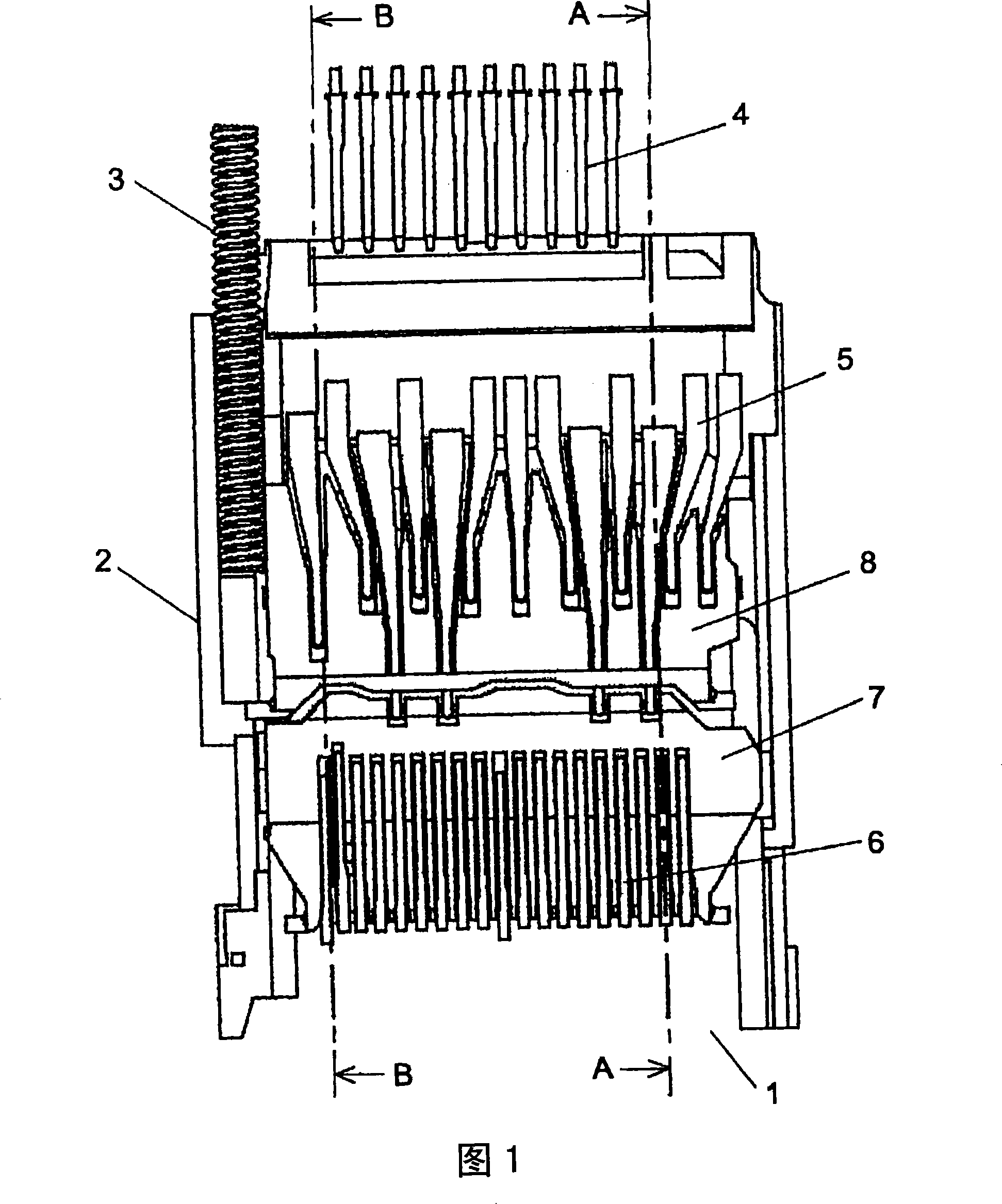
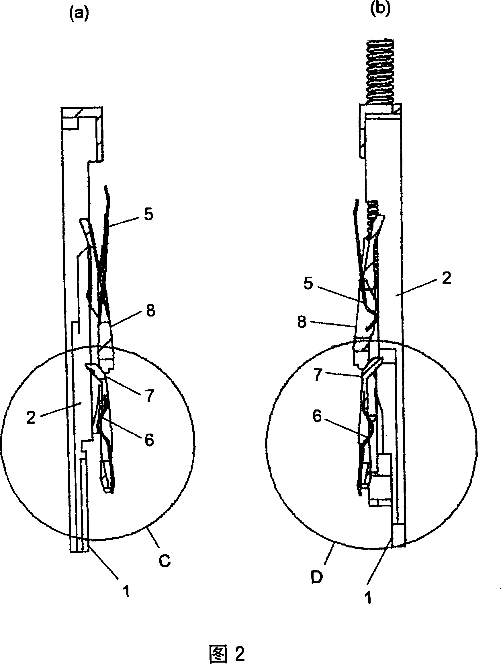
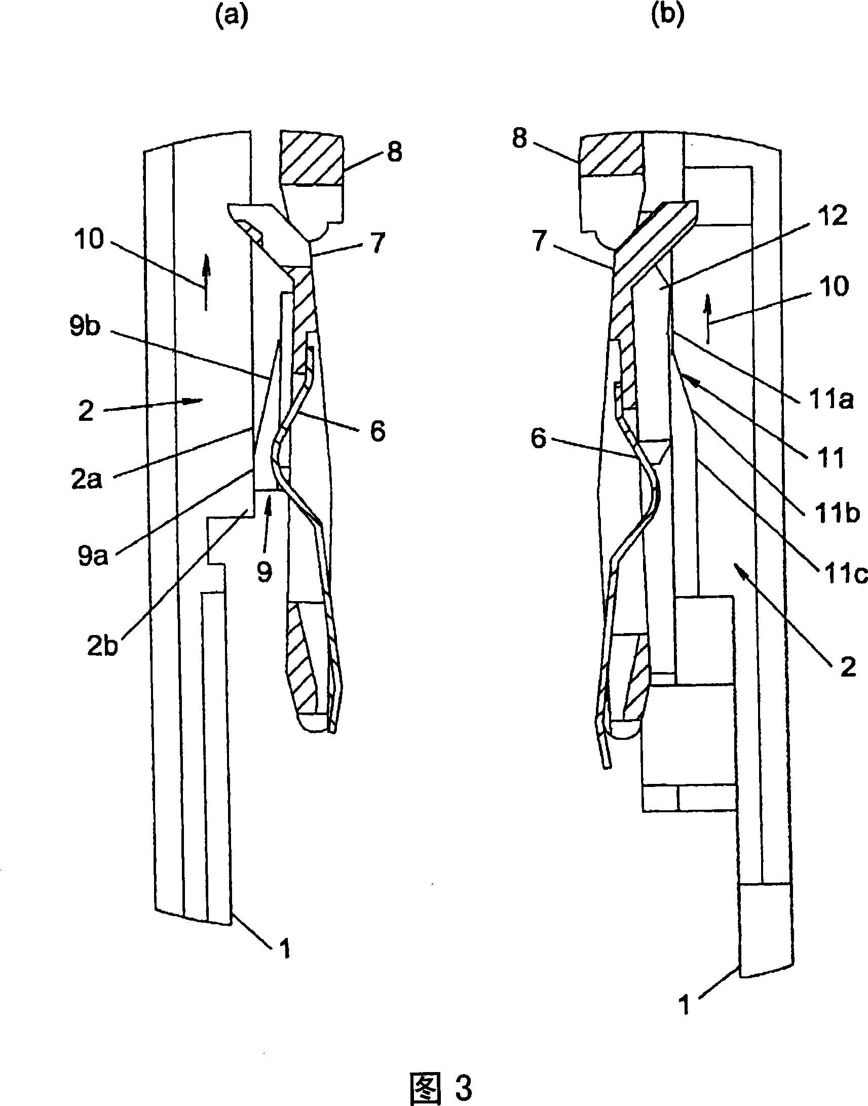
[0037] Fig. 1 is a main part plan view showing an embodiment of the card connector device of the present invention, Fig. 2 is a side sectional view of Fig. 1 , (a) is a sectional view of A-A of Fig. 1 , (b) is Fig. 1 The B-B section diagram. 3 is an enlarged view showing the main part of FIG. 2 , (a) is an enlarged view of part C of (a) of FIG. 2 , and (b) is an enlarged view of part D of (b) of FIG. 2 . Fig. 4 is a diagram showing a state in which a wrongly inserted card is inserted in this embodiment, (a) is a plan view of main parts, and (b) is a sectional view taken along line E-E of (a).

[0038] This embodiment can insert a variety of cards such as: a long and thick first card 21 described later that is installed in a prescribed first card installation part inside the device; The first ...


PUM


Abstract

PROBLEM TO BE SOLVED: To provide a connector device for a card in which an erroneous insertion card can be easily taken out from a card insertion port even if an erroneous insertion card is inserted. ŽSOLUTION: The connector device is provided with a first cam plate 7 which is urged to the direction going to a card insertion passage 10 by an urging force by a third contact terminal 6 and, when a first and a second cards 21, 22 are inserted, is rotated in the direction to be separated from the card insertion passage 10, thereby moves the third contact terminal 6 from the card insertion passage 10. Furthermore, a holding means which, when the first, the second, and a third cards 21, 22, 23 are at a waiting state not being inserted from the card insertion port 1, holds the first cam plate 7 in a rotated state in the direction separating from the card insertion passage 10 against the urging force of the third contact terminal 6 is provided. Ž

Description

technical field [0001] The present invention relates to a card connector device capable of mounting various types of cards of different lengths and having a cam plate capable of moving contact terminals located on the front side of the device in a direction away from a card insertion path. Background technique [0002] As such a prior art, there exists what is described in patent document 1. Patent Document 1 discloses a card connector device capable of mounting various types of cards, such as relatively long and thick cards and short and thin cards. [0003] This prior art has: a card insertion port that allows the above-mentioned cards to be inserted respectively; a plurality of first contact terminals arranged inside the device and capable of contacting the contact portion of the above-mentioned elongated card; A plurality of second contact terminals contacted by the contact portion of the short card. It also includes a slide member that slides in an insertion direction...

Claims


Application Information

Patent Timeline
IPC IPC(8): H01R13/629H01R12/16G06K17/00
Inventor 峠馆广美
Owner ALPS ALPINE CO LTD
Learn More