Eureka AIR delivers breakthrough ideas for toughest innovation challenges, trusted by R&D personnel around the world.

Fuel pump and filter assembly

A filter assembly, fuel pump technology, used in engine components, machines/engines, liquid fuel feeders, etc.

Inactive Publication Date: 2008-05-14
TI集团自动推进系统有限责任公司
View PDF2 Cites 6 Cited by
  • Summary
  • Abstract
  • Description
  • Claims
  • Application Information

AI Technical Summary

Problems solved by technology

But this approach generally requires extensive retooling to provide a compatible design for each individual vehicle application

Method used


Image

  • Fuel pump and filter assembly
  • Fuel pump and filter assembly
  • Fuel pump and filter assembly

Examples


Embodiment Construction

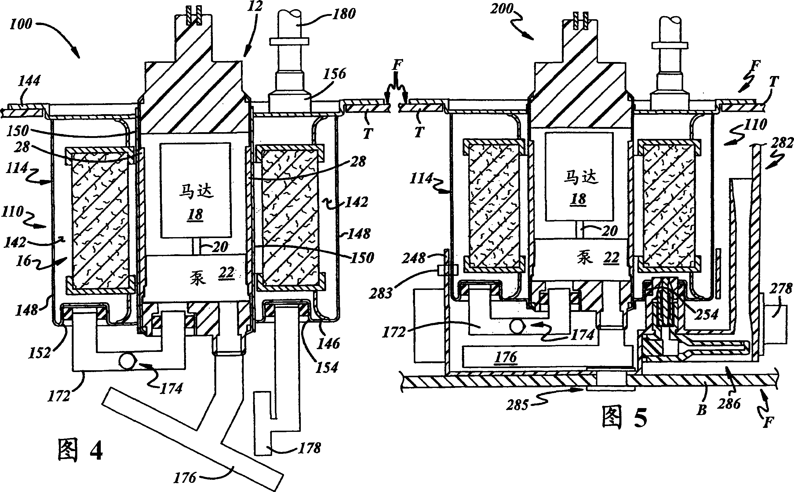
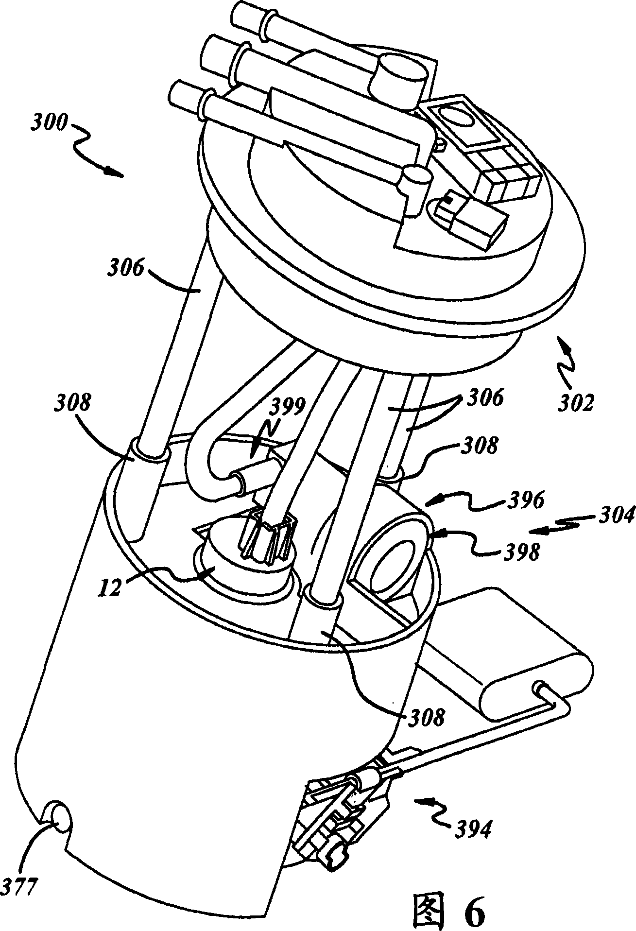
[0019] Referring to the drawings in more detail, FIGS. 1-3 illustrate a presently preferred form of a fuel pump and filter assembly 10 for drawing fuel from a fuel tank (not shown) and pressurizing and Fuel is filtered for delivery to the engine (not shown). As best shown in Figure 3, assembly 10 includes a fuel pump assembly 12 for pumping and pressurizing fuel, a housing 14 for carrying fuel pump assembly 12, and a housing 14 for filtering fuel from the fuel pump assembly 14 carried in housing 14. Filter 16 for pressurized fuel received at pump assembly 12 . Assembly 10 may be used alone or in conjunction with a fuel pump module (not shown) for insertion into a fuel tank.

[0020] Fuel pump assembly 12 may be any suitable pump device, such as an electromechanical pump device, that pressurizes fuel for delivery to the upstream or inlet side of filter 16 . Fuel pump assembly 12 is centrally positioned relative to filter 16 and housing 14 such that filter 16 and housing 14 su...


PUM


Abstract

A fuel pump and filter assembly includes a housing supporting a filter in a filter chamber, which is at least partially defined by first and second end walls, an outer wall extending therebetween, and an inner side wall disposed radially inwardly of the outer side wall. A fuel pump assembly is carried by the housing radially inwardly of the inner side wall and includes a sleeve that extends from the first end wall of the housing to the second end wall of the housing.

Description

technical field [0001] The present invention relates generally to fuel pumps, and more particularly to fuel pump modules for placement in fuel tanks. Background technique [0002] In-tank fuel pump modules are used in automotive fuel delivery systems to draw fuel from the fuel tank and supply fuel under pressure for delivery to the engine. These modules generally comprise a fuel reservoir disposed in the fuel tank and carried by a mounting plate or flange closing an opening in the upper wall of the tank. The reservoir holds a relatively small quantity of fuel and typically includes a reservoir inlet that communicates with the interior of the fuel tank. [0003] The module typically includes an electric fuel pump assembly having a pump inlet downstream of the reservoir in communication with the reservoir inlet at one end, and a pump outlet upstream of the reservoir outlet at the other end. A fuel pump assembly draws fuel from the reservoir through the fuel pump inlet and de...

Claims


Application Information

Patent Timeline
Patent Type & Authority Applications(China)
IPC IPC(8): F02M37/14F02M37/22F02M37/44F02M37/50
CPCF02M37/10F02M2037/225F02M37/22F02M37/44F02M37/50
Inventor L·F·克拉里A·J·达西尔瓦P·P·库佩鲁斯
Owner TI集团自动推进系统有限责任公司
Why Eureka
Eureka Blog
Learn More