
Lens module

A lens module and lens barrel technology, applied in installation, optics, instruments, etc., can solve problems such as affecting imaging effects, gaps, and the inability of lens modules to meet imaging requirements.

Inactive Publication Date: 2008-04-30
HONG FU JIN PRECISION IND (SHENZHEN) CO LTD +1
View PDF0 Cites 5 Cited by
  • Summary
  • Abstract
  • Description
  • Claims
  • Application Information

AI Technical Summary

Problems solved by technology

[0004] However, for the lens module installed outdoors or on the vehicle body, when the ambient temperature changes, the water vapor in the surrounding environment will condense on the surface of the lens module, making the lens module unable to meet the expected imaging requirements
In addition, for the lens module itself, the internal components of the lens barrel will also shrink or expand beyond the expected design due to temperature changes, causing gaps and affecting the imaging effect

Method used


Image

  • Lens module
  • Lens module
  • Lens module

Examples


Embodiment Construction

[0011] The present invention will be described in further detail below in conjunction with the accompanying drawings.

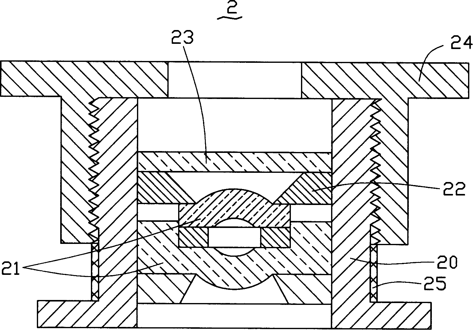
[0012] In the following embodiments of the lens module, the heating device is arranged on the outer surface of the lens barrel.

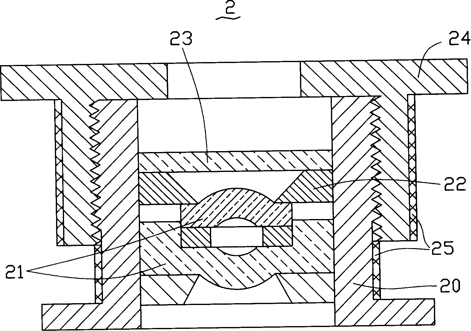
[0013] see figure 2 , The lens module 2 of the present invention includes a lens base 24 , a lens barrel 20 matched with the lens base 24 , a plurality of optical elements and a heating device 25 . In this embodiment, the plurality of optical elements include at least one lens group 21, a spacer ring 22, and a filter 23, wherein the lens group 21, the spacer ring 22, and the filter 23 are sequentially fixed on the mirror along the optical axis direction. In the barrel 20, the filter 23 is arranged on the outermost side of the lens barrel 20 close to the object to be irradiated. The cooperation between the mirror base 24 and the lens barrel 20 is a fixed connection or a threaded connection. Threaded connection is adopted in this...


PUM


Abstract

The invention relates to a lens mould set which comprises a lens seat, a lens cone which is matched with the lens seat, a plurality of optical elements and a heating device, wherein, a plurality of optical elements are orderly fixed in the lens cone along the direction of optical axis. The heating device is arranged at the outer surface of the lens cone and / or the lens seat. The lens mould set can not generate the phenomenon of moisture condensation when the temperature is changed. In addition, the lens mould set can prevent the phenomenon that gaps can appear caused by the material of each element is not consistent and shrinkage-expansion is not consistent.

Description

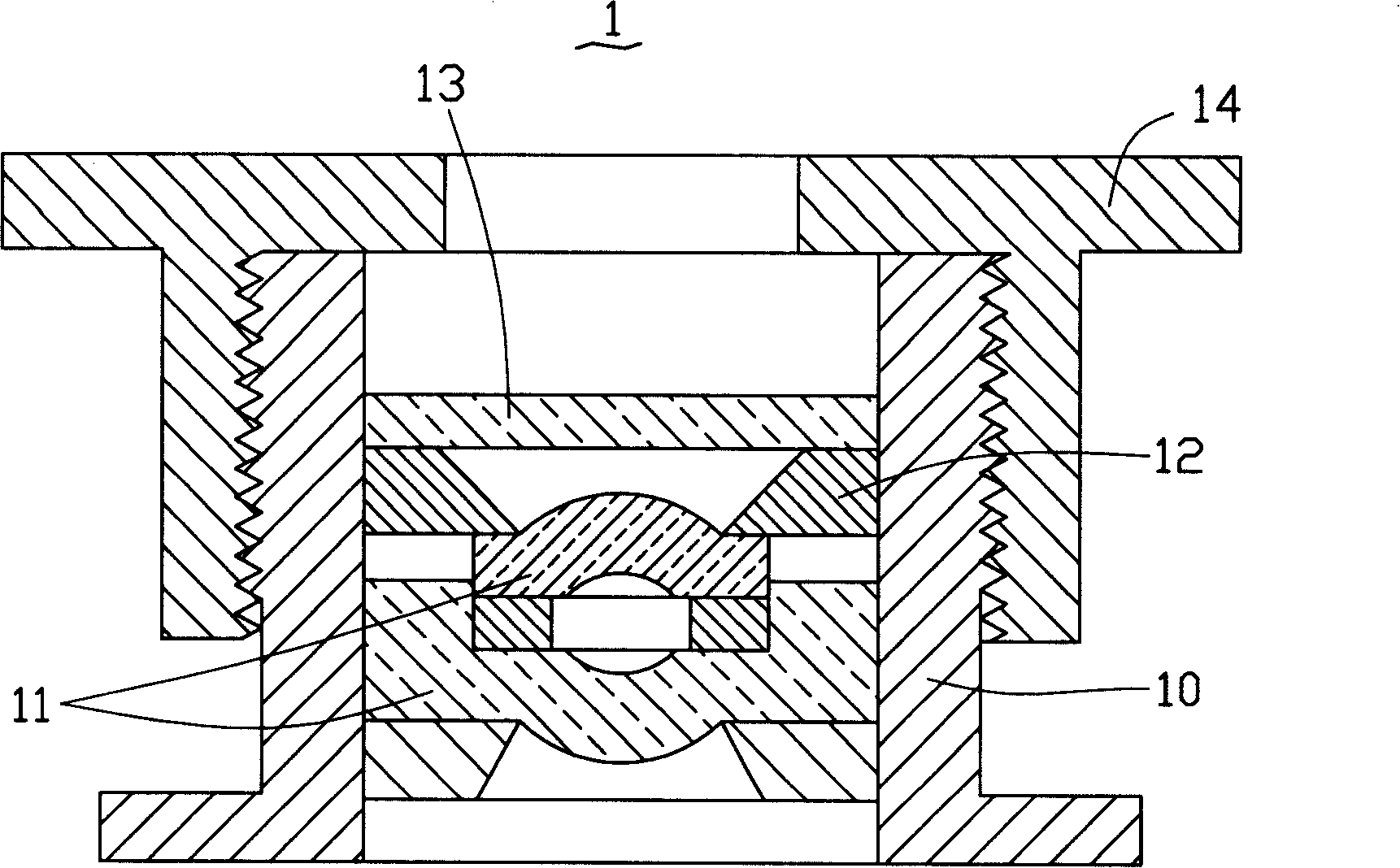
technical field [0001] The invention relates to an imaging device, in particular to a lens module. Background technique [0002] With the development of optical imaging technology, lens modules are widely used in various imaging devices such as digital cameras and video cameras, and mobile phones, notebooks and automobiles integrated with lens modules are favored by many consumers. A lens module with a shooting function is generally composed of lenses and mechanical components. For high-quality lenses, in order to ensure the imaging quality, the position of each component should be fixed, so a good assembly method should be used for assembly to ensure a relatively stable positional relationship between the components, so that they will not fall off. So as to ensure that the lens has good imaging quality. [0003] Please refer to figure 1 , the lens module 1 in the prior art includes a mirror base 14, a lens barrel 10 screwed with the mirror base 14, a lens group 11, a spa...

Claims


Application Information

Patent Timeline
Patent Type & Authority Applications(China)
IPC IPC(8): G02B7/02
CPCG02B7/028
Inventor 袁崐益
Owner HONG FU JIN PRECISION IND (SHENZHEN) CO LTD
Learn More