
Integrated torsional mode damping system and method

A vibration damping system, torsional vibration technology, applied in the control system, reducing/preventing power oscillation, transportation and packaging, etc., can solve the problems that are not suitable for connecting to the commutation converter system of the grid

Inactive Publication Date: 2008-04-16
GENERAL ELECTRIC CO
View PDF0 Cites 16 Cited by
  • Summary
  • Abstract
  • Description
  • Claims
  • Application Information

AI Technical Summary

Problems solved by technology

These three-phase systems are not suitable for connection to additional grid-commutated converter systems

Method used


Image

  • Integrated torsional mode damping system and method
  • Integrated torsional mode damping system and method
  • Integrated torsional mode damping system and method

Examples


Embodiment Construction

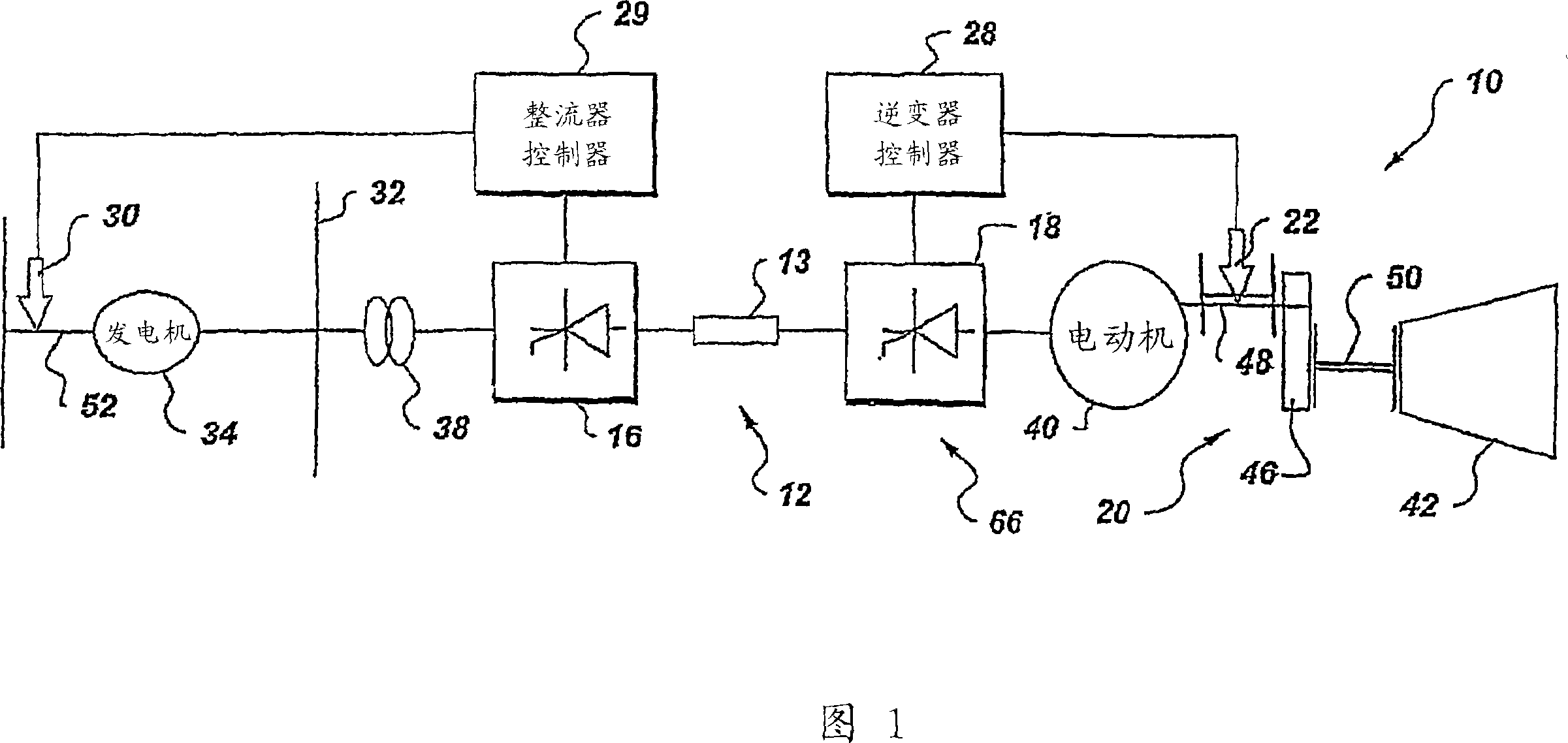
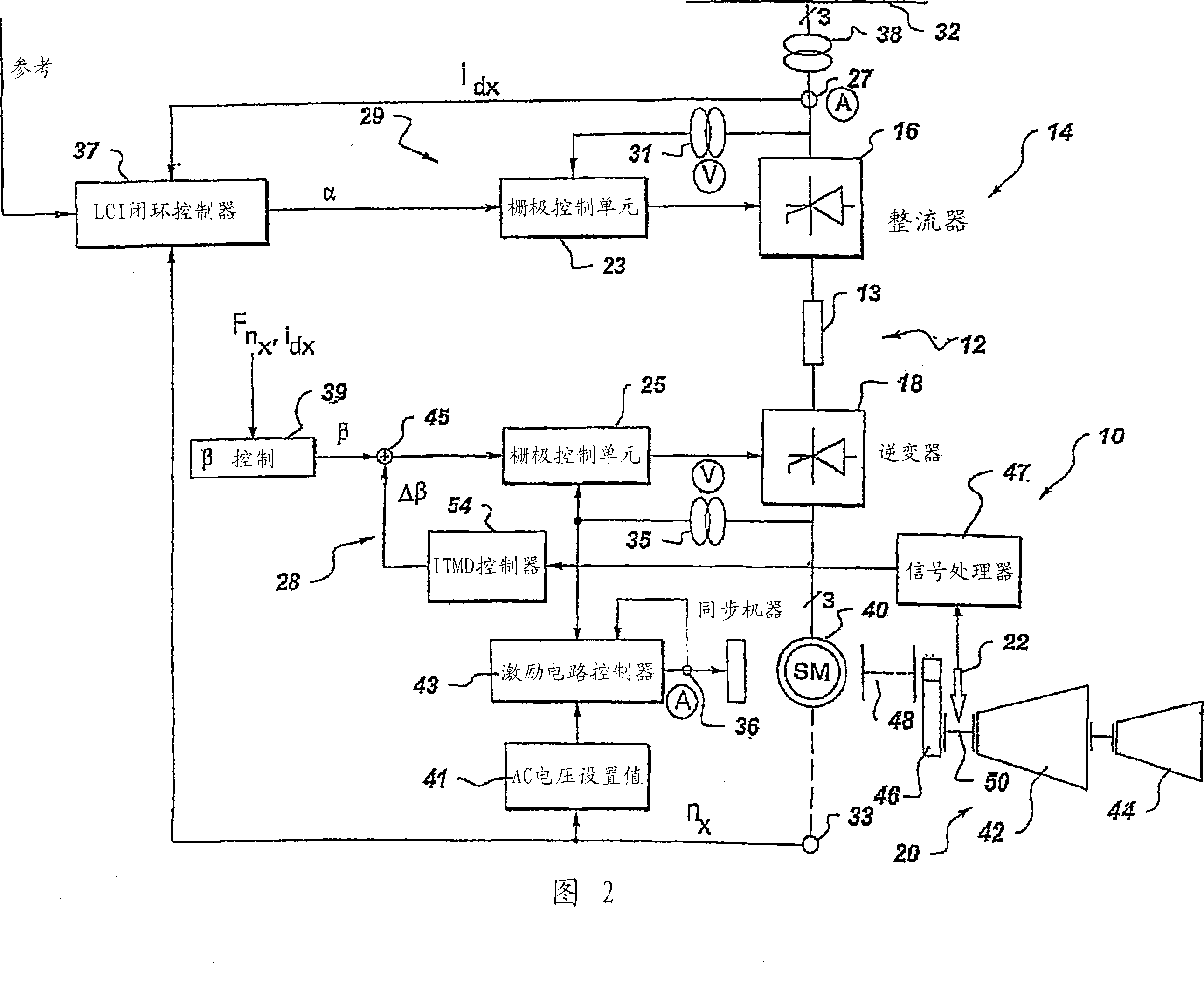
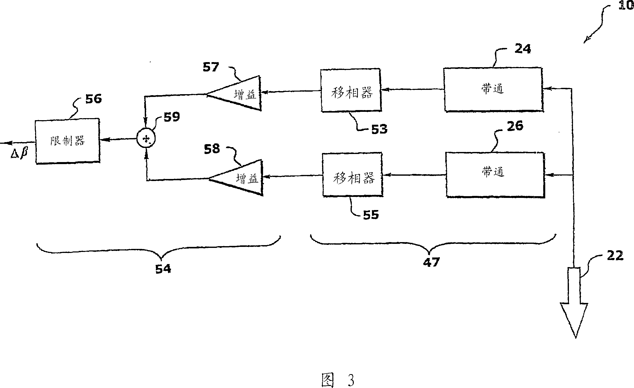
[0023] FIG. 1 is a block diagram of a system 10 for reducing torsional vibrations according to one embodiment of the present invention. Although the examples described with reference to FIGS. 2-8 relate primarily to transmission line network and load embodiments with load-commutated inverter systems, the principles are also applicable to embodiments including rectifier 16, inverter 18, and coupling between rectifier 16 and inverter. Any current source converter 66 embodiment with DC link inductor 13 between converter 18. Typically, rectifier 16 and inverter 18 comprise thyristor type converters.

[0024] Whether the shaft is sensed on the rectifier side (represented by shaft 52 ) or on the inverter side (represented generally by shaft 20 and more specifically by shaft portions 48 and 50 ), Any of these embodiments can be applied. In one embodiment, the method of damping vibration includes using either sensor 22 or 30 (meaning at least one) to sense a signal representative of...


PUM


Abstract

An integrated torsional mode damping method for a current source converter comprising a rectifier, an inverter and a DC link inductor coupled between the rectifier and inverter, the method comprising: sensing a signal representative of torque on a shaft coupled to the inverter or rectifier; using the sensed signal to detect the presence of torsional vibrations on the shaft; and by regulating real power via the corresponding inverter or rectifier to reduce the torsional vibration.

Description

technical field [0001] The present invention generally relates to reducing torsional vibration. Background technique [0002] A shaft assembly in a shaft string comprising prime movers and loads of turbine generators, electric motors or compressors sometimes exhibits weakly damped mechanical resonances (torsional mode ). If the grid exchanges a substantial amount of energy with the generator at one or more of the shaft system's natural frequencies, mechanical damage can occur over time. Traditional countermeasures against the phenomenon of torsional resonance include efforts to eliminate the resonance excitation source by, for example, changing network, operating or control parameters. [0003] Electric loads on the power system have only negligible influence when the power system is connected to a large utility network with billions of watts of generating power. In contrast, islanded power systems have no connection to a large power network, and quasi-islanded power syst...

Claims


Application Information

Patent Timeline
Patent Type & Authority Applications(China)
IPC IPC(8): H02P9/10H02J3/24
CPCH02P2009/004Y02T10/6217B60L2270/145Y02T10/70H02P9/10B60L11/123Y02T10/7077Y02T10/642H02P29/0038B60L2220/14B60L50/61H02P2101/15H02P29/50Y02T10/62Y02T10/64Y02T10/7072
Inventor 克里斯托夫·M·西勒约瑟夫·桑
Owner GENERAL ELECTRIC CO
Learn More