
Measurement and correction method for inertia confinement complete light path aberration of fusion device

A technology of inertial confinement fusion and correction method, which is applied in the field of measurement and correction of full optical path aberration, and can solve problems such as the inability to realize full optical path aberration correction

Inactive Publication Date: 2008-04-16
INST OF OPTICS & ELECTRONICS - CHINESE ACAD OF SCI
View PDF0 Cites 11 Cited by
  • Summary
  • Abstract
  • Description
  • Claims
  • Application Information

AI Technical Summary

Problems solved by technology

[0005] The technical problem of the present invention is: to overcome the deficiencies of the prior art, to provide a method for measuring and correcting the full optical path aberration of the inertial confinement fusion device, which can realize the detection and control of the full optical path aberration, which not only makes up for The hill-climbing method has the disadvantage of slow correction of aberrations, and overcomes the disadvantage that the aberration measurement in the near field of the system cannot achieve full optical path aberration correction

Method used


Image

  • Measurement and correction method for inertia confinement complete light path aberration of fusion device
  • Measurement and correction method for inertia confinement complete light path aberration of fusion device
  • Measurement and correction method for inertia confinement complete light path aberration of fusion device

Examples


Embodiment Construction

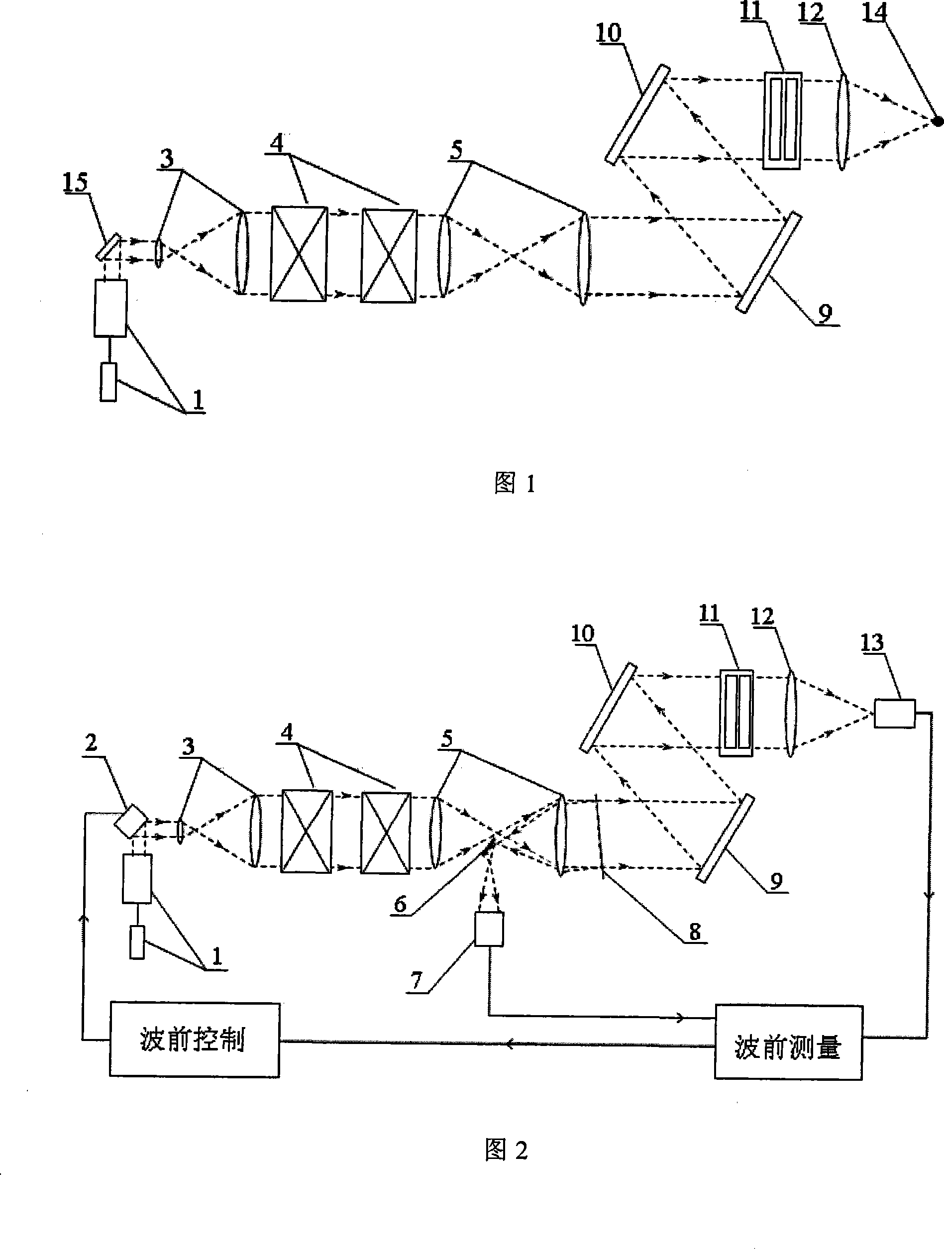
[0045] As shown in Figure 1, it is a schematic structural diagram of the optical path principle of a typical ICF device. The seed light source is emitted from the front end, reflected by the mirror 15 and introduced into the optical matching system 3, and then the energy is amplified after passing through the laser amplifier 4, and then introduced into the optical matching system 5, and then The frequency doubling crystal 11 is introduced through the transmission mirrors 9 and 10 , and then focused on the target pill 14 by the focusing lens 12 .

[0046] FIG. 2 is a schematic structural diagram of an ICF device equipped with the system of the present invention. The reflective deformable mirror 2 replaces the reflector 15; the light leak mirror 8 splits and samples light in the near field, and the sampling beam is guided into the H-S wavefront sensor 7 through the reflector 6, and the H-S wavefront sensor 7 can measure the aberration of the main optical path before the light lea...


PUM


Abstract

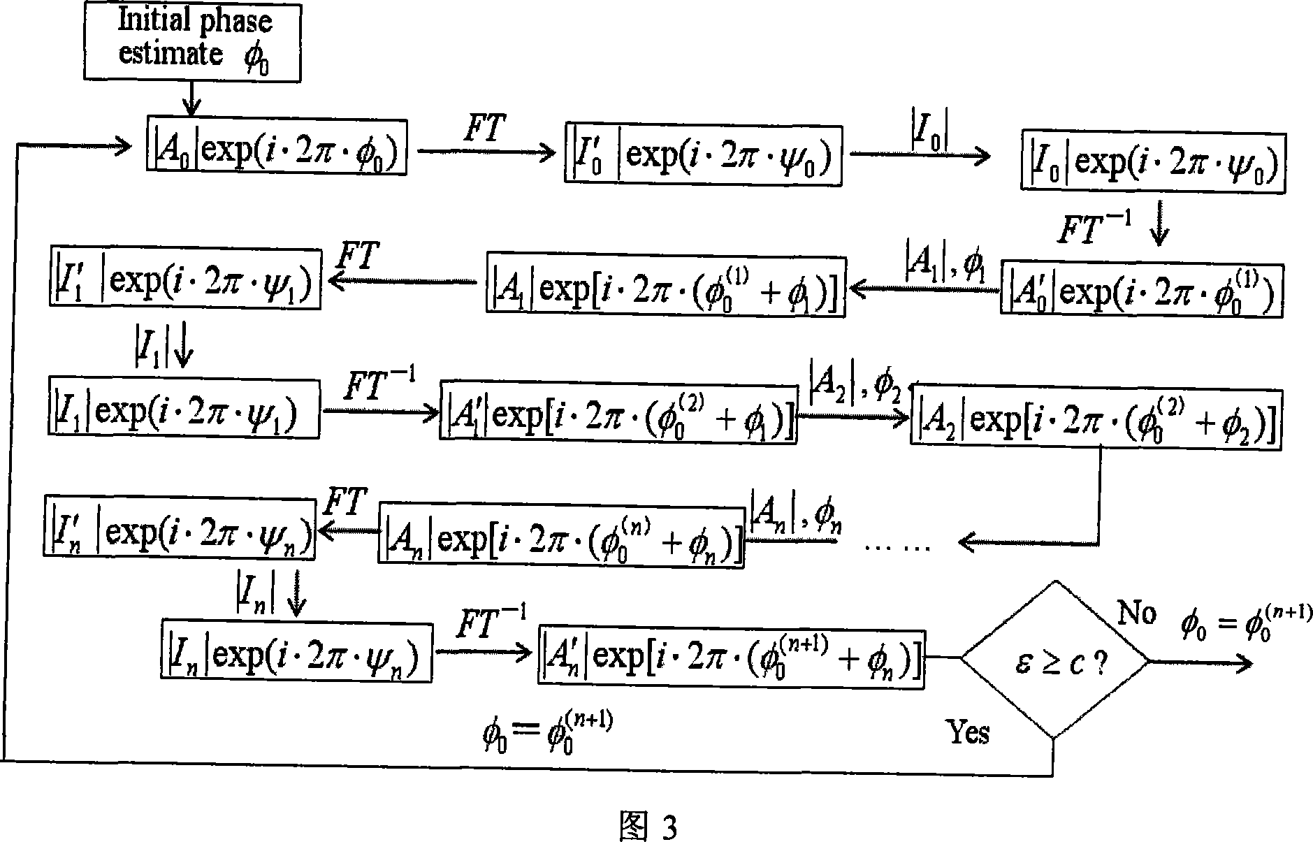
The invention discloses a measurement and correction method of entire beam path aberration for an inertial confinement fusion device, wherein, a Hartmann wave-front sensor is arranged in the beam path behind a laser amplifier for detecting the near field wave-front; a reflection deformable mirror is arranged in the beam path before the Hartmann wave-front sensor, a CCD is arranged in the entire beam path far field for detecting the strength distribution of the focal spot; the dynamic aberration is directly measured by the Hartmann wave-front sensor, the static aberration is jointly measured by the reflection deformable mirror, the Hartmann wave-front sensor and the far field CCD which are matched with each other; when the reflection deformable mirror is driven, the Hartmann wave-front sensor records different wave-fronts modulated by the deformable mirror; at the same time, the far field CCD records the corresponding far field strength; according to the recorded different near field modulated wave-fronts and the corresponding far field strength data pairs, the entire beam path static aberration of the inertial confinement fusion device is calculated by the iterated algorithm, which drives the reflection deformable mirror to correct the aberration. The invention realizes the measurement and correction of entire beam path aberration for the ICF device.

Description

technical field [0001] The invention relates to a method for measuring and correcting the full optical path aberration of an inertial confinement fusion device. Background technique [0002] In the inertial confinement fusion device ICF, in order to meet the needs of shooting, there are high requirements on the quality of the beam, especially the energy concentration or the shape of the focal spot in the far field of the beam. The existence of optical aberration will lead to uncontrollable far-field focal spots, thereby reducing the effectiveness of laser bombardment of the target capsule, which puts forward high requirements for the control of wavefront distortion of the optical system. Adaptive optics technology is an effective means of correcting optical system aberrations, and it is currently used in ICF systems in various countries. There are generally two types of adaptive optics aberration correction methods in ICF setups: [0003] The first type is the hill-climbin...

Claims


Application Information

Patent Timeline
IPC IPC(8): G02B26/06
Inventor 敖明武杨平蔡冬梅杨泽平饶长辉姜文汉
Owner INST OF OPTICS & ELECTRONICS - CHINESE ACAD OF SCI
Learn More