
Gas kitchen range and gas generator supplying gas to the same

A gas stove and gas technology, which is applied to coke ovens, biofuels, household stoves/stoves, etc., can solve the problems that the firepower is difficult to achieve the expected effect, the purification effect is not ideal, the gas stove pipeline is blocked, etc. Easy to clean and improve the effect of firepower

Inactive Publication Date: 2008-04-16
湖南中正机电设备有限公司
View PDF0 Cites 2 Cited by
  • Summary
  • Abstract
  • Description
  • Claims
  • Application Information

AI Technical Summary

Problems solved by technology

Theoretically speaking, this kind of energy conversion is feasible, and it is also a good way to turn waste into wealth and save energy. It is more convenient and hygienic to use; There are still some bottlenecks in realizing this transformation: firstly, the adaptability of gas stoves. Most of the gas stoves used in existing gas stoves are similar to liquefied petroleum gas stoves or biogas stoves. The combustible gas contains a large amount of tar, which is not only difficult to burn cleanly, but also accumulates in the pipeline in the gas stove. This tar will form a hard tar scale after cooling, so it will be burned in a short period of time. The pipeline in the gas stove is blocked; at the same time, due to the low pressure of the combustible gas generated by the gas generator, it is difficult to achieve the desired effect when burning
Secondly, although the existing various gas generators are equipped with gas purification devices during the gas production process, most of them use simple cooling and deceleration principles to achieve purification, so the purification effect is not ideal. Still contain a higher concentration of water and tar

Method used


Image

  • Gas kitchen range and gas generator supplying gas to the same
  • Gas kitchen range and gas generator supplying gas to the same
  • Gas kitchen range and gas generator supplying gas to the same

Examples


Embodiment Construction

[0028] The present invention will be further described below in conjunction with the accompanying drawings and embodiments.

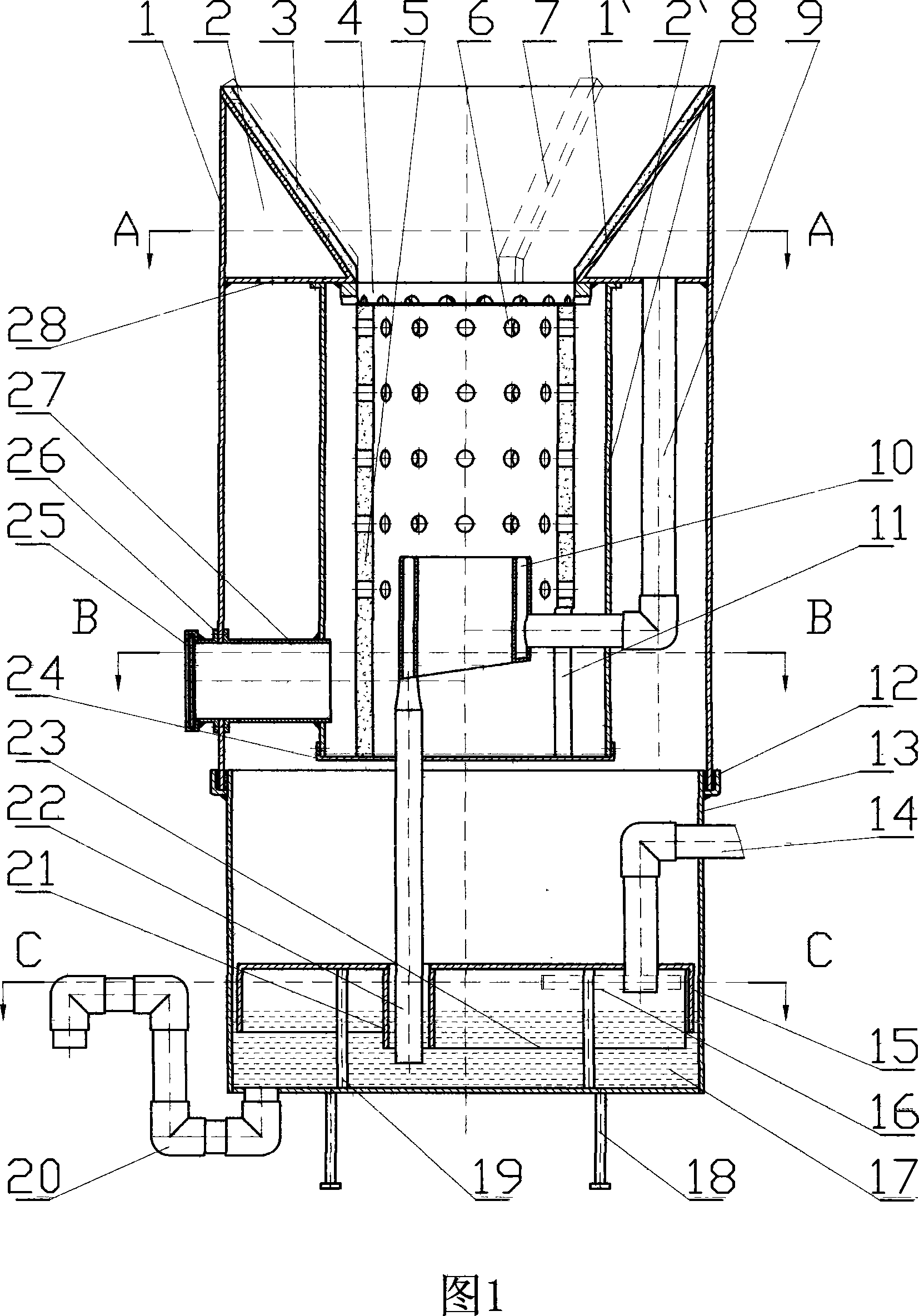
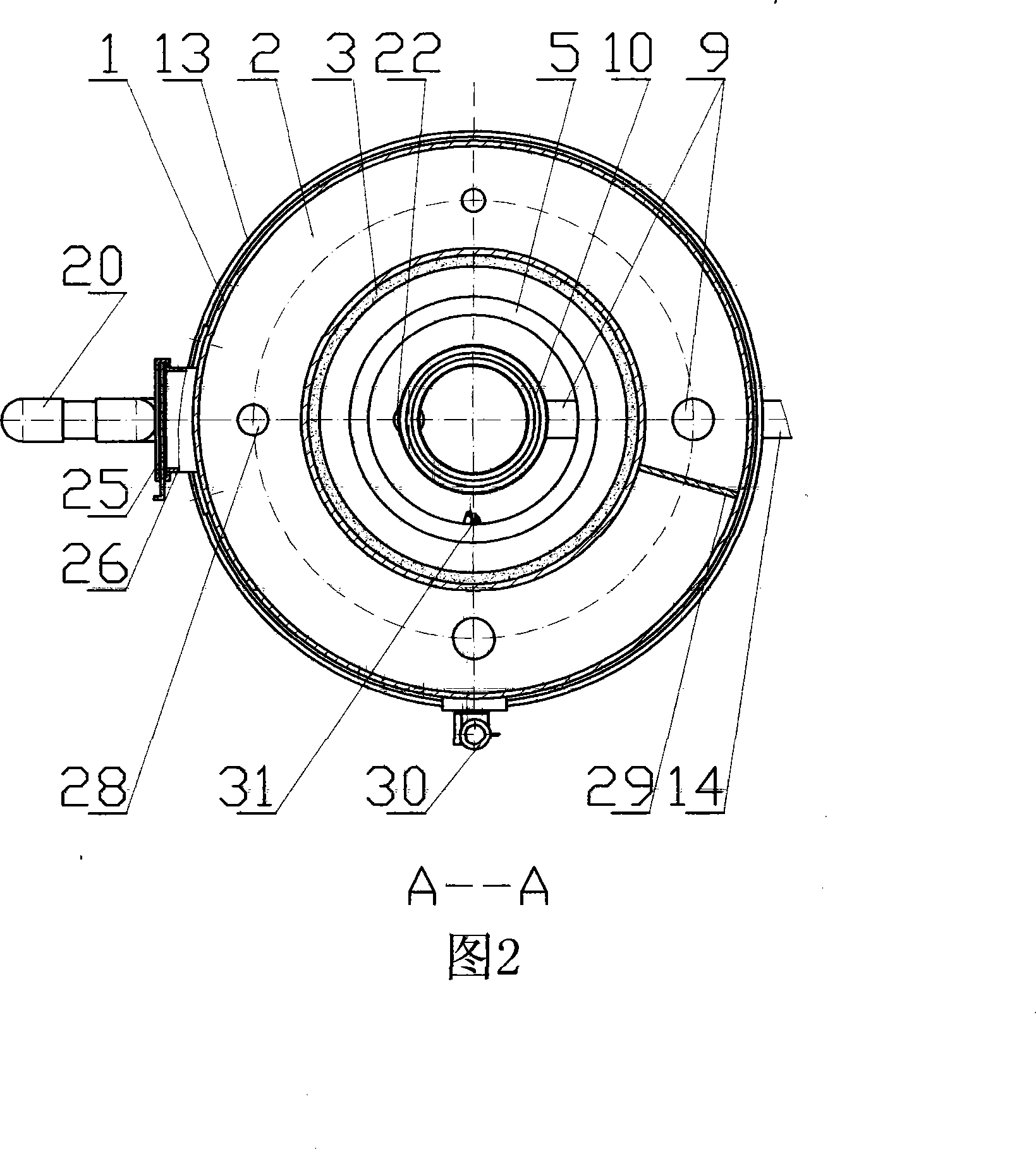
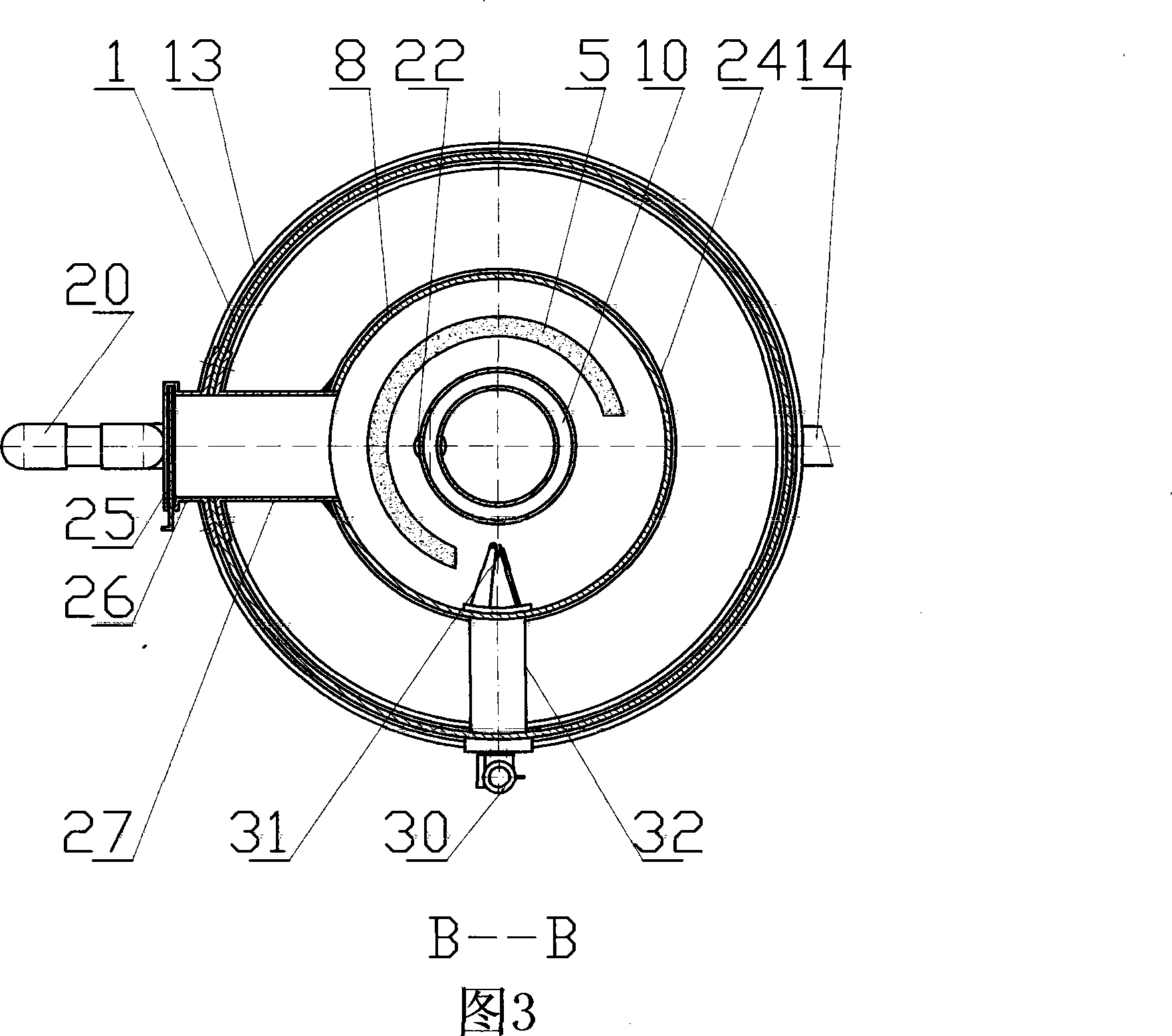
[0029] The gas stove of the present invention is composed of a stove body 1, a stove body 5, a pan bar 7, a hot and cold gas isolation cover 8, a hot gas guide pipe 9, a gas uniform distributor 10, a gas purification cylinder 13, an air intake pipe 14, a gas purification Disc 15, stove foot 18, tar discharge pipe 20, tar guide pipe 22, outer air inlet cylinder 26 and inner air inlet cylinder 27 and ignition device 30 constitute.

[0030] The stove body 1 is a cylinder, and its upper end forms an inner conical gas preheating cavity 2 with a triangular inner cavity section with the ring plate 2` and the conical cylinder 1`. The upper conical surface of the conical cylinder 1` is covered with Refractory layer kitchen range wall 3, the top device of kitchen range wall 3 puts pot bar 7, is used for shelving cooking all. There are four air inlet holes 28 on ...


PUM


Abstract

The invention discloses a gas range and a generating furnace supplying gas for the gas range, relating to the industrial and household range field; the gas range consists of a range body(1), a range barrel body(5), a cold-hot gas shielding cover(8), a gas applicator(10), a gas purification barrel(11), an air inlet pipe(14), a gas purification disc(15), rang feet(18), a tar discharge pipe(20), a tar guiding pipe(22), an outer air inlet barrel(26) and an ignition device(30); the generating furnace consists of a furnace barrel body(44), a furnace core(61), an air duct(50), a hot water bucket(42), a furnace cover(35), a back taper place(37), a liquid drainage groove(38), an air applicator(51) and a sealing palace-type gas purification device; the invention has the advantages of convenient use and maintenance, high conversion efficiency of fuel, good effect of gas purification and strong fire power, etc.; the invention can fully use the agriculture crop wastes or flammable industrial and household wastes, thereby the invention is suitable to be used not only by dwellers in rural areas and small towns, but also by enterprises and institutions; moreover, the invention can also be used to dispose wastes for heat supply.

Description

technical field [0001] The invention relates to the field of industrial and domestic furnaces, in particular to a gas generator and a gas stove capable of generating gas from crop waste or combustible industrial and domestic waste. Background technique [0002] In the prior art, there are many gas generating stoves that use crop waste or combustible industrial and domestic waste to generate gas. The working principle is: the combustible substances in the furnace will be converted into combustible gas under high temperature and oxygen-deficient conditions , and then burn these combustible gases to realize energy conversion. Theoretically speaking, this kind of energy conversion is feasible, and it is also a good way to turn waste into wealth and save energy. It is more convenient and hygienic to use; There are still some bottlenecks in realizing this transformation: firstly, the adaptability of gas stoves. Most of the gas stoves used in existing gas stoves are similar to liq...

Claims


Application Information

Patent Timeline
Patent Type & Authority Applications(China)
IPC IPC(8): F24B1/18C10B53/02F24B1/191F24B1/197
CPCY02B40/166Y02E50/14Y02B40/00Y02E50/10
Inventor 唐常清
Owner 湖南中正机电设备有限公司
Learn More