Yield highly effective oil-well pump for mechanical oil production

A technology for mechanical oil extraction and oil pumping, which is applied in mechanical equipment, liquid variable capacity machinery, pumps, etc., can solve the problems of increased leakage, failure of the oil well pump, stuck plunger, etc., to reduce the impact of gas on the pump, Prevent liquid strike and air lock phenomenon and ensure the effect of matching clearance

Inactive Publication Date: 2010-08-18
国营第三八八厂
View PDF0 Cites 0 Cited by
  • Summary
  • Abstract
  • Description
  • Claims
  • Application Information

AI Technical Summary

Problems solved by technology

[0003] (1) Due to the use of metal hard-sealed plungers, affected by machining errors, in order to ensure that the plunger moves briskly and flexibly in the pump barrel, the designed fit between the plunger and the pump barrel is relatively large, resulting in the cooperation between the plunger and the pump barrel during oil production The oil leakage in the gap is high, and the pump efficiency is low
[0004] (2) When the sand and sundries in the oil enter the gap between the metal plunger and the pump barrel, they will become abrasives for abrasive wear, causing rapid wear of the pump barrel and plunger. Since the metal plunger is not compensatory, Therefore, the matching clearance increases, the leakage increases, and the pump efficiency decreases
When the sand or debris particles are large, the plunger will also be stuck, causing the oil well pump to fail
[0005] (3) Opening lag of the floating valve (that is, the oil outlet valve)
Since the liquid column pressure of the tubing is far greater than the weight of the floating valve ball, and the deeper the lower pump is, the greater the pressure will be. Therefore, in practice, the opening hysteresis of the floating valve is very serious, resulting in the loss of effective stroke and the reduction of pump efficiency.
[0006] (4) The opening of the fixed valve (that is, the oil inlet valve) lags
When the dynamic liquid level is low and the submergence is small, the opening of the fixed valve will lag behind, resulting in the loss of effective stroke and the reduction of pump efficiency
[0007] (5) When the oil contains gas, the released dissolved gas will be filled in the pump cavity. During the downstroke and upstroke, the gas will be compressed and expanded in the pump cavity, making the opening hysteresis of the valve ball more obvious and serious. Liquid hammer and air lock will occur when the oil pump fails, and cause serious impact on the entire oil pumping system

Method used


Image

  • Yield highly effective oil-well pump for mechanical oil production
  • Yield highly effective oil-well pump for mechanical oil production
  • Yield highly effective oil-well pump for mechanical oil production

Examples


Embodiment Construction

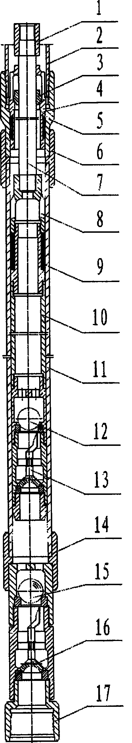
[0023] In the present invention, the soft seal plunger 9 is connected with the hard seal plunger 10, the upper part of the plunger is connected with the valve stem 7 through the upper open valve cover 8, the upper part of the valve stem is connected with the valve stem joint 1; the lower part of the plunger is connected with the oil outlet valve 12 , the lower part of the oil outlet valve is connected to the oil outlet speed opening valve 13.

[0024] The plunger is fitted with a pump barrel 11, the upper part of the pump barrel is connected to the support joint 5 through the upper pump barrel collar 6, and the upper part of the support joint is connected to the oil pipe 2; the lower part of the pump barrel is connected to the oil inlet valve 15 through the lower pump barrel collar 14, and the oil inlet The lower part of the valve is connected to the oil inlet quick opening valve 16, and the lower part of the oil inlet quick opening valve is connected to the oil inlet valve joi...


PUM


Abstract

The invention discloses a deep well tube pump for raw oil exploration in oil field. Through adopting the composite structure of a flexible seal plunger piston and a hard seal plunger piston, adding a quick-opening valve under an inlet valve and a delivery valve, designing a biased valve on the upper part of a pump barrel, etc. the invention is characterized by low leakage, high filling degree, long effective stroke, long high yielding period and service life, stronger function of air prevention and sand prevention, can effectively improve oil well yield and is applicable to common explorationof general oil wells and oil extraction of worse well conditions such as gassy oil well, sandy oil well and so on.

Description

technical field [0001] The invention relates to a deep well tubular oil well pump used for oil field mechanical exploitation of crude oil, and is a rod oil production equipment. It is suitable for oil production in conventional oil wells and oil wells with poor gas and sand-bearing conditions. It can effectively improve the pump efficiency and increase the production of oil wells. Background technique [0002] At present, conventional tubular oil well pumps are mainly composed of tie rods, metal hard-sealed plungers, pump barrels and fixed valves, and the upstream and downstream moving valves are distributed at the upper and lower ends of the plunger. Practice has proved that the oil well pump with this structure has low oil production efficiency and short production cycle. The main reasons are as follows: [0003] (1) Due to the use of metal hard-sealed plungers, affected by machining errors, in order to ensure that the plunger moves briskly and flexibly in the pump barrel...

Claims


Application Information

Patent Timeline
Patent Type & Authority Patents(China)
IPC IPC(8): F04B47/02F04B53/14F04B53/12E21B43/00
Inventor 胡桢刘建魁李进玉高宏陈行文
Owner 国营第三八八厂
Why Eureka
Try Eureka