
Sole member

A component and bottom surface technology, applied in the directions of soles, footwear, applications, etc., can solve the problems such as the inability to fully suppress the deterioration of deformable knee joint disease, the inability to fully relieve the impact force of the heel, and the inability to achieve the effect of wearing comfort, etc. Effects of deterioration of osteoarthritis deformity, prevention of osteoarthritis deformity, and comfortable walking

Active Publication Date: 2008-04-02
ASAHI KK
View PDF2 Cites 0 Cited by
  • Summary
  • Abstract
  • Description
  • Claims
  • Application Information

AI Technical Summary

Problems solved by technology

However, when each rib bears weight pressure, it tilts from its root at once, so a torque is suddenly generated, and the impact force when the heel hits the ground cannot be sufficiently relieved, so there is a problem that the aggravation of deformed knee joint disease cannot be sufficiently suppressed. Defects
[0009] In addition, although healthy people can prevent deformed knee joint disease after wearing shoes with such a sole member installed on the bottom surface of the heel, as mentioned above, a sudden torque will be brought to the calf when walking, so it will affect the use of The person brings uncomfortable feeling, and there is such a defect that the effect of wearing comfort cannot be achieved.

Method used


Image

  • Sole member
  • Sole member
  • Sole member

Examples


Embodiment Construction

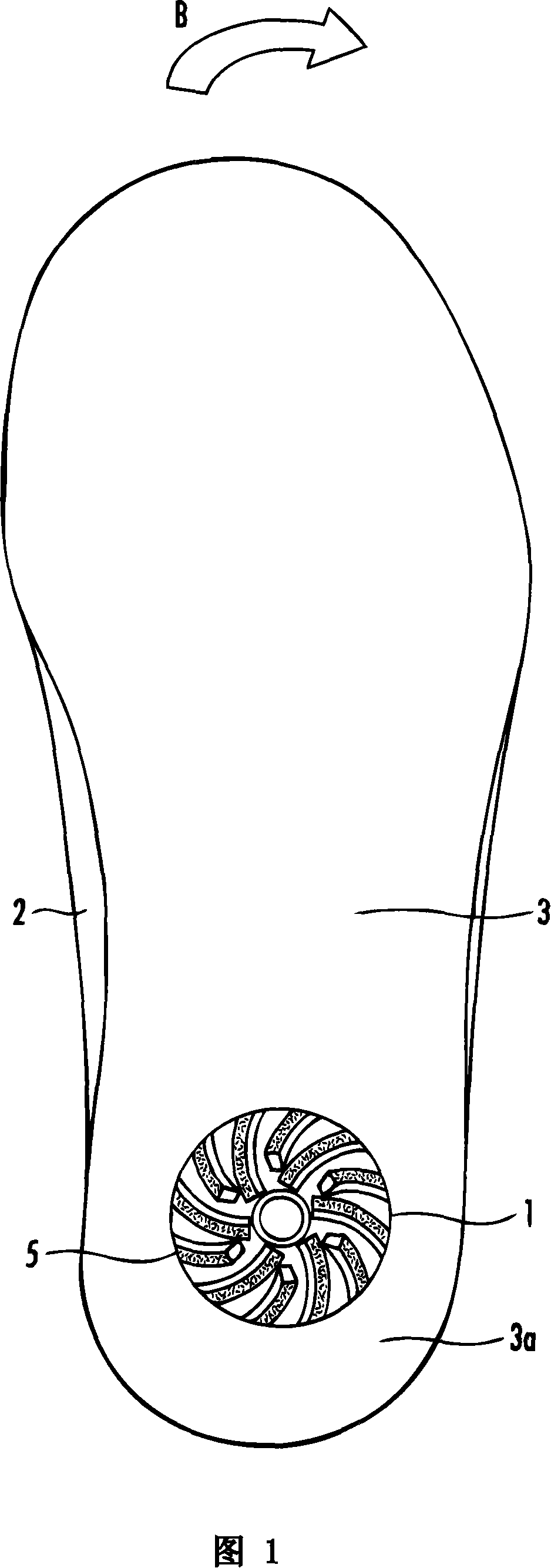
[0033] An embodiment of the present invention will be described with reference to FIGS. 1 to 4 . As shown in FIG. 1 , a sole member 1 according to the present embodiment is attached to a ground of a shoe 2 , that is, a heel 3 a of a sole 3 .

[0034] First, the structure of the sole member 1 will be described.

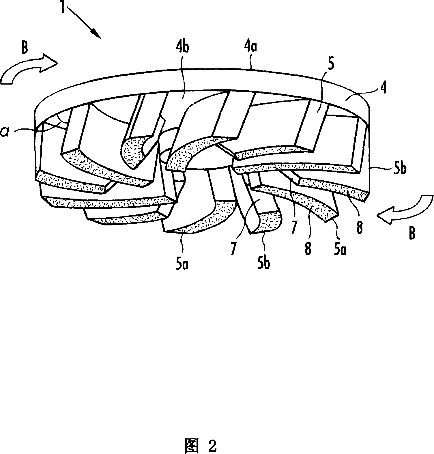
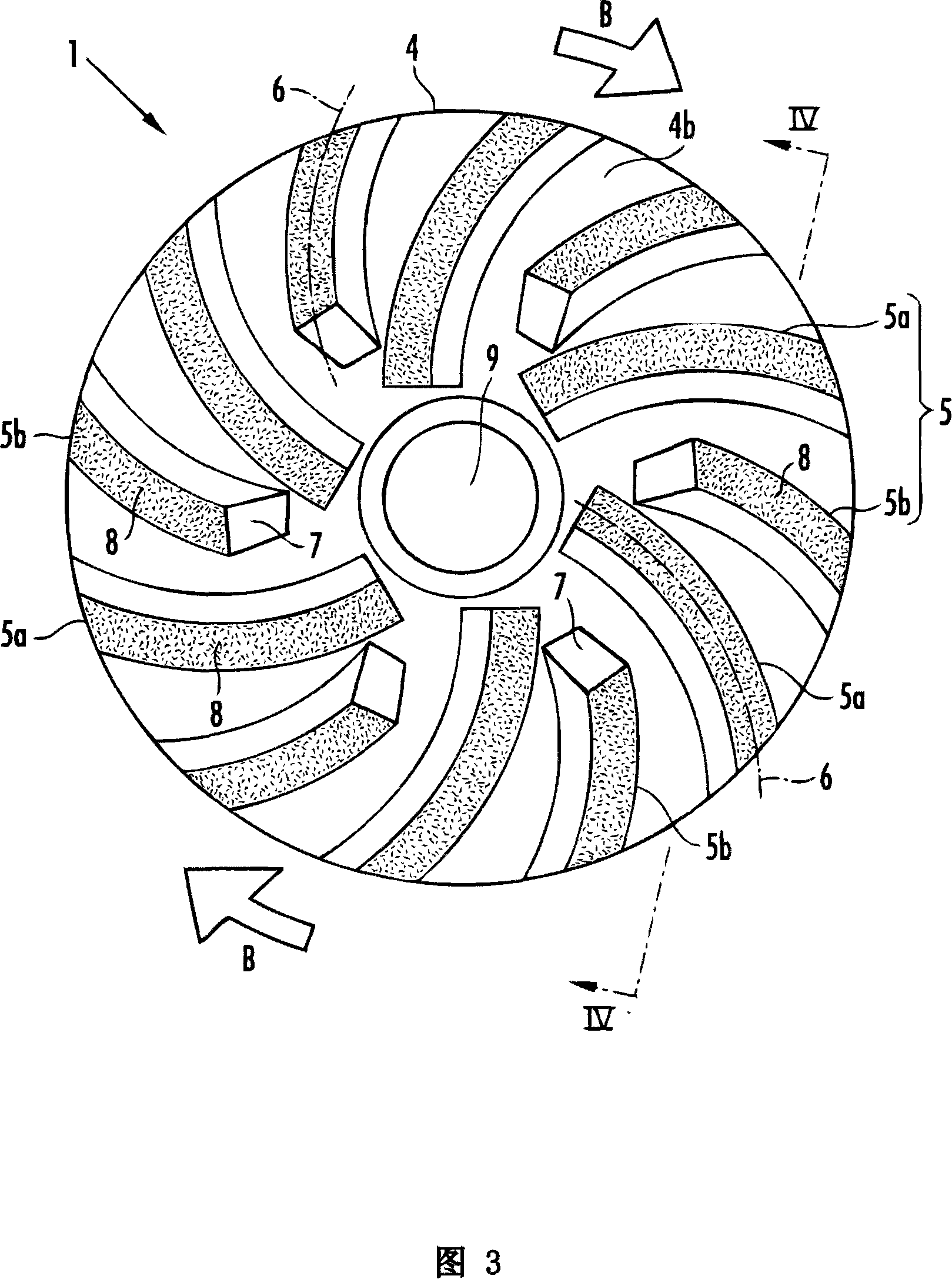
[0035]The sole member 1 is molded from a rubber composition such as natural rubber or synthetic rubber. As shown in FIGS. 2 and 3 , it has a base 4 and a plurality of ribs 5 (a plurality of first ribs 5 a and a plurality of second ribs 5 b ). The base 4 is in the shape of a flat disc, and its top surface 4a is joined with the sole 3 to form a single body.

[0036] As shown in FIG. 4 , each rib 5 is provided integrally with the bottom surface 4 b of the base 4 , and protrudes while being inclined toward the landing direction (downward). As shown in FIG. 3 , the ribs 5 extend radially, are arranged at predetermined intervals in the circumferential direction, and are c...


PUM


Abstract

The present invention provides a shoe sole member mounted on the bottom surface of the heel of the shoe sole. By reliably alleviating the impact force when the heel hits the ground, a gentle torque is generated, thereby effectively suppressing the deterioration of deformed knee joint disease. In addition, healthy people In order to prevent osteoarthritis, you can also walk comfortably without discomfort. It includes a base (4) and a plurality of elastic ribs (5), and the base 4 is fixed on the bottom surface of the heel (3a) of the shoe sole (3) during use. The ribs (5) are inclined in the same direction from the base (4) toward the ground surface, protrude and extend radially, and are arranged at predetermined intervals in the circumferential direction. Each rib (5) is formed in a curved shape in the radial direction, so each rib (5) bends and tilts gradually according to the body weight pressure at the time of landing, thereby mitigating the impact and producing a gentle rotation in the horizontal direction with the ground. moment.

Description

technical field [0001] The present invention relates to a shoe sole member, which is installed on the bottom surface of the heel of the shoe sole to generate torque in a direction horizontal to the ground due to the body weight pressure when the foot is on the ground. Background technique [0002] Usually, when the knee moves, it needs to stretch and bend (bend, extend), and the articular surface of the knee also needs to do sliding and rotating motions. The knee joint is the weight-bearing joint of the lower body and plays an important role in support and movement. The knee joint is the joint between the femur, the tibia, and the kneecap. In order to prevent direct friction between the bones, the joint between the bones is covered with a layer of articular cartilage. In the gap between the femur and the tibia is a crescent-shaped cartilage called the meniscus, which acts as a buffer to absorb shock. It is said that the impact load on the joints during walking is three tim...

Claims


Application Information

Patent Timeline
Patent Type & Authority Applications(China)
IPC IPC(8): A43B13/14
CPCA43B3/0042A43B13/14
Inventor 日高滋纪木下信博塚本裕二山崎伸一平川和生江西浩一郎
Owner ASAHI KK
Learn More