
Sound-reproducing transducer

A sound reproduction and transducer technology, applied in the direction of transducer housing/cabinet/bracket, sensor, electrical components, etc., can solve the problem of insufficient sound reproduction quality and achieve satisfactory sound effect

Inactive Publication Date: 2008-03-26
ALCATEL LUCENT SAS
View PDF0 Cites 0 Cited by
  • Summary
  • Abstract
  • Description
  • Claims
  • Application Information

AI Technical Summary

Problems solved by technology

[0015] These vibrations create audible sound, resulting in less than good quality sound reproduction

Method used


Image

  • Sound-reproducing transducer
  • Sound-reproducing transducer

Examples


Embodiment Construction

[0030] In the hints of the description, the invention is described as being applied to a radiotelephone or mobile telephone.

[0031] More generally it also applies to all types of radio transceivers, such as radio pagers, personal digital assistants (PDAs) or laptop computers.

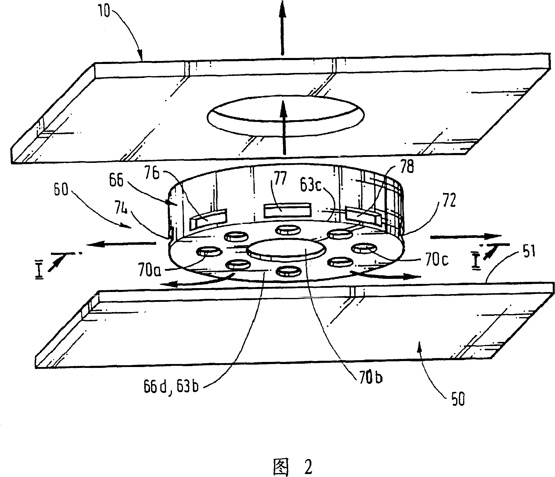
[0032] Referring to FIG. 2, the general shape of transducer 60 is a hollow cylinder with an outer cylindrical wall 66 defined by two opposing circular faces, namely two generally planar front faces 66c and back faces 66d.

[0033] These faces 66c, 66d are substantially parallel to each other.

[0034] The circular front face 66c constitutes the front face 63a of the transducer 60 . The circular back face 66d constitutes the back face 63b of the transducer 60 .

[0035] Diaphragm 64 of transducer 60 , which will be described in more detail hereinafter, is located between and substantially parallel to circular front face 66 c and circular rear face 66 d , at about half the height of the outer side wal...


PUM


Abstract

The invention relates to a sound-reproducing transducer ( 60 ) connected to a printed circuit ( 50 ). This transducer ( 60 ) has the shape of a hollow cylinder whose cylindrical wall ( 66 ) delimits two circular faces, one front face ( 66 c) and one rear face ( 66 d) that are opposed and planar. The transducer ( 60 ) comprises at least one diaphragm ( 64 ) that makes it possible to convert electric signals into sound waves and conversely. This diaphragm ( 64 ) is a circular membrane parallel to the front face ( 66 c) and rear face ( 66 d) of the transducer ( 60 ). The diaphragm ( 64 ) delimits two distinct volumes in the transducer ( 60 ), the first volume being bordered on one side by the circular face ( 66 c) of the transducer ( 60 ) and on the other by the diaphragm ( 64 ) while forming a front acoustic cavity ( 61 ), and the second volume being bordered on one side by the circular face ( 66 d) of the transducer ( 60 ) and on the other by the diaphragm ( 64 ) while forming a rear acoustic cavity ( 62 ). The invention is characterized in that the cylindrical wall ( 66 ) of the transducer ( 60 ) has at least one perforation ( 72, 74, 76, 77, 78 ).

Description

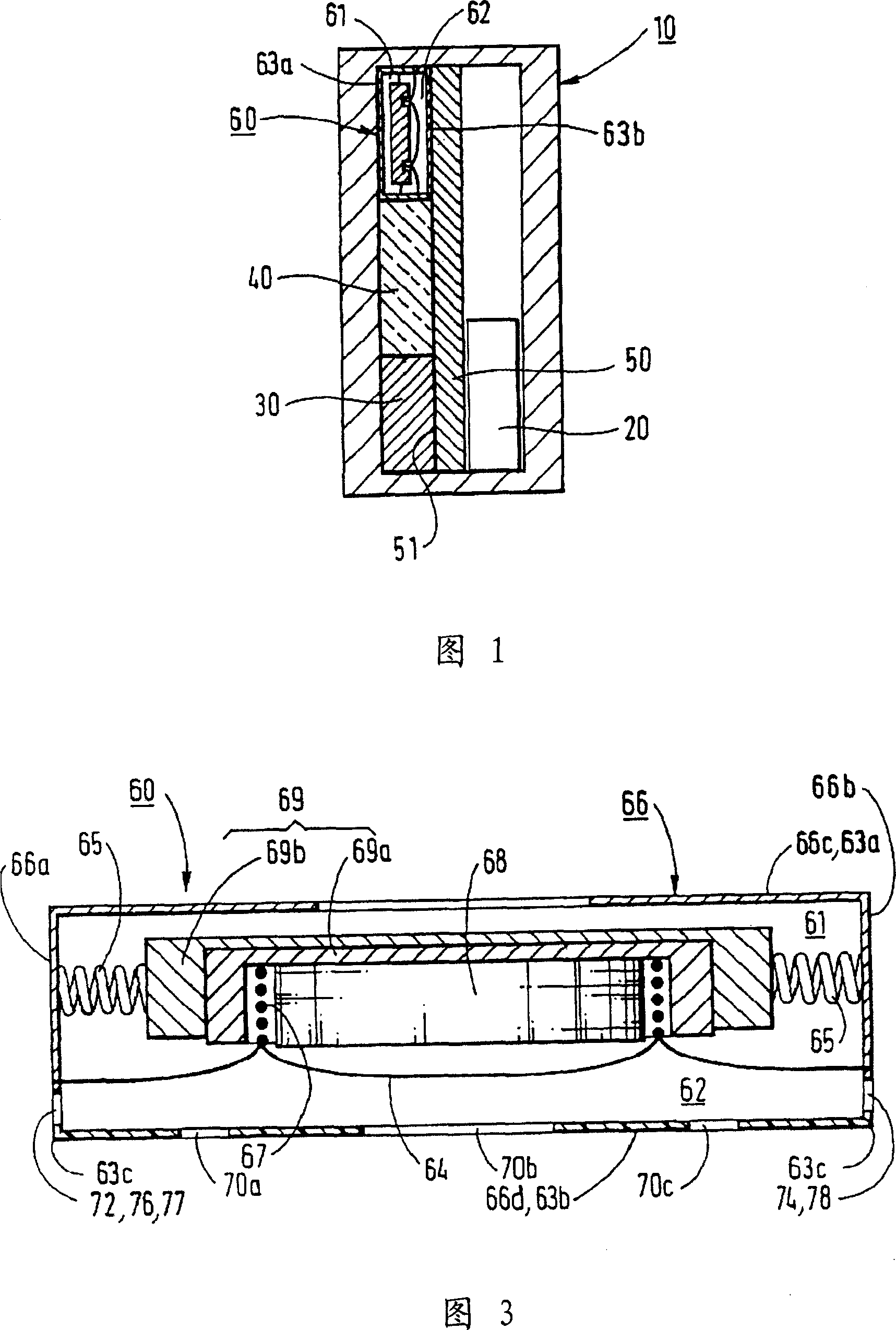
technical field [0001] The invention relates to a sound reproduction transducer connected to a printed circuit, and to a terminal comprising such a transducer. [0002] One but not the only field of application of the invention is mobile radio communication terminals. Background technique [0003] Manufacturers of mobile communication terminals are currently seeking to make them as small as possible while maintaining optimum ergonomics. [0004] The optimization of the dimensions of the terminals, shown schematically in side view in Figure 1, has pushed manufacturers to reduce their thickness. [0005] The mobile terminal comprises a housing 10 in which various components are arranged, such as a battery 20 , a keypad 30 , a screen 40 and a sound reproduction transducer 60 connected to a printed circuit 50 . [0006] The sound reproduction transducer or sound transducer 60 is adapted to convert electrical signals supplied to it into sound signals and vice versa. [0007] T...

Claims


Application Information

Patent Timeline
Patent Type & Authority Applications(China)
IPC IPC(8): H04R1/02H04Q7/32H04R9/06
CPCH04R9/06
Inventor 斯蒂芬·杜富斯让-克里斯托弗·维莱恩埃里克·梅纽伊维斯·莱鲍杜尔
Owner ALCATEL LUCENT SAS
Learn More