Ventilating current equalizer

A technology of flow equalizer and ventilation duct, which is applied in the field of uniform outflow or uniform inhalation pipeline, which can solve problems such as errors, inability to achieve uniform airflow at the tuyere, and inability to achieve uniform air supply and exhaust, etc., achieving low cost, simple structure, and convenient construction and the effect of installing

Active Publication Date: 2008-03-26
CHINA RAILWAY ERYUAN ENG GRP CO LTD
View PDF0 Cites 14 Cited by
  • Summary
  • Abstract
  • Description
  • Claims
  • Application Information

AI Technical Summary

Problems solved by technology

[0004] The current uniform air supply and exhaust methods objectively have inevitable errors in design calculations and on-site construction; at the same time, there are obvious defects that only maintain the "equal" airflow through the tuyere, but cannot truly achieve uniform airflow through the tuyere.
The implementation effect of the existing method is not ideal in terms of uniform air supply and exhaust, and when the distance of uniform air supply or exhaust is required to reach a certain length, the purpose of uniform air supply and exhaust will not be achieved

Method used


Image

  • Ventilating current equalizer
  • Ventilating current equalizer
  • Ventilating current equalizer

Examples


Embodiment 1

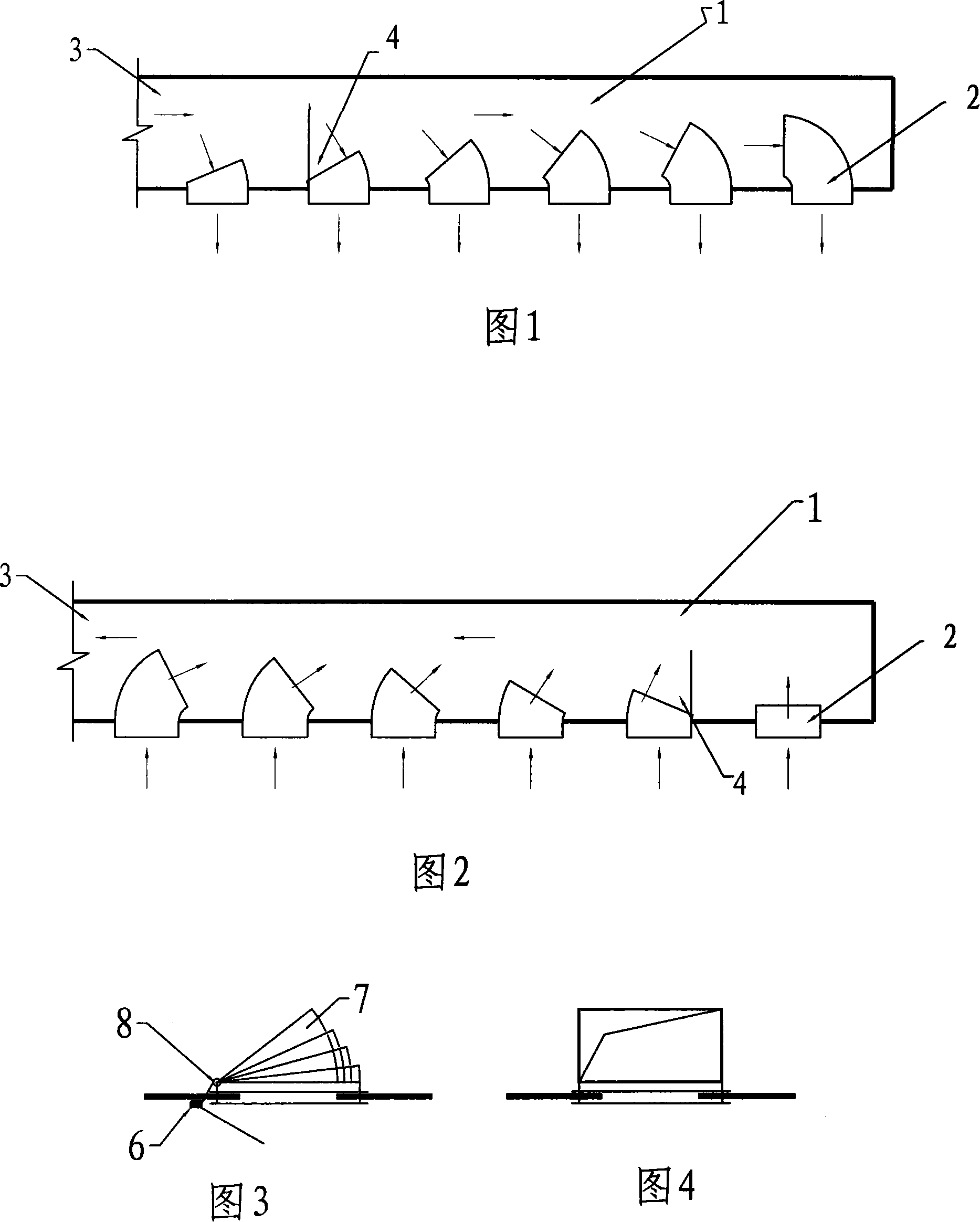
[0023] As shown in FIG. 1 , the ventilation duct 1 is an air supply duct, and the windward section on the tuyere 2 faces the starting end 3 of the duct. The projected area of ​​the windward section of the tuyeres 2 arranged in sequence according to the starting end 3 on the cross section of the air supply duct 1 increases successively, that is, the included wind inlet angle 4 decreases successively. Each tuyere 2 intercepts the dynamic pressure in the pipe through the adjustment of the air inlet angle 4 to make up for the shortage of the outlet pressure of the tuyere until the actual demand of the outlet air volume of the tuyere is met.

[0024] As shown in Figure 2, the ventilation duct 1 is an exhaust duct, and the windward section on the tuyere 2 faces away from the starting end 3 of the duct, and the projection of the windward section on the tuyere 2 arranged in sequence according to the starting end 3 on the section of the air supply duct 1 The area decreases successively...

Embodiment 2

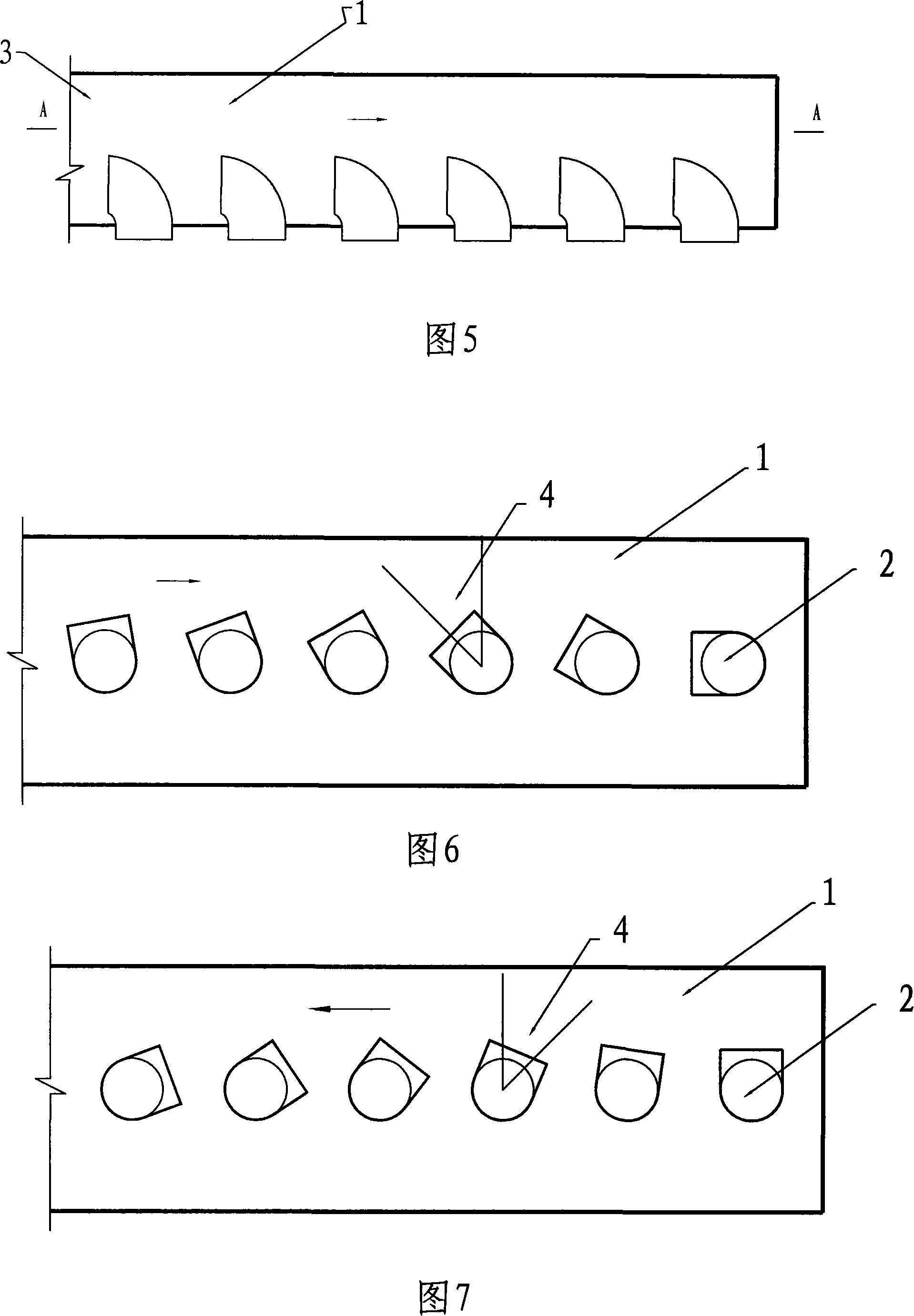
[0027] As shown in Figure 5 and Figure 6, it is another improved embodiment of the present invention. The ventilation duct 1 is a uniform air supply duct, and the tuyere 2 adjusts its windward cross section and duct cross section sequentially from the starting end 3 through its own axial rotation. The air inlet angle 4 increases sequentially to change the dynamic pressure in the intercepting pipe and keep each air outlet to obtain the same pressure to achieve uniform air flow out of the air supply pipe. When the ventilation duct 1 is an exhaust duct, as shown in FIG. 7 , the angle 4 between the windward section and the duct section is sequentially adjusted from the starting end 3 to decrease successively, so as to realize uniform suction of the uniform exhaust duct.

[0028] In order to facilitate the adjustment of the air inlet angle 4 of each tuyere 2, the tuyere 2 is a complete 90° circular air duct elbow, its structure and installation form are shown in Figure 8 and Figure ...


PUM


Abstract

This invention discloses a air supplying and discharging pipeline, especially an evenly absorbing and discharging pipeline that is adequate for long distance air supplying and discharging pipeline. It includes a simple and convenient ventilation flow equalizer, which is composed of several air ports arranged on the ventilation pipeline. The projecting area of the air port windward sections on air supplying pipeline section are increased or decreased successively. The flow rate and pressure of air port can be adjusted according to the position of air port, in order to realize evenly discharging or absorbing of the air supplying pipeline. This invention is easy to assemble too.

Description

technical field [0001] The invention relates to an air supply and exhaust pipeline, especially a pipeline suitable for uniform outflow or uniform suction in long-distance air supply and exhaust pipelines. Background technique [0002] In the uniform air supply and exhaust duct, as the duct diverges due to the air supply or the confluence of the suction and exhaust air, and the distance changes, the pressure inside the air duct changes accordingly. Therefore, necessary measures are required to maintain the same flow rate for each tuyere from the beginning to the end of the air duct. [0003] In order to ensure that the flow rate of each air outlet is the same and achieve the purpose of uniform flow, the current method used is: for the air supply duct, one is to design the air supply duct as a variable cross-section air duct, and the other is to keep the cross section of the air supply duct unchanged. Change the area of ​​the air outlet; for the exhaust duct, the only way to ...

Claims


Application Information

Patent Timeline
Patent Type & Authority Applications(China)
IPC IPC(8): F24F13/065
Inventor 钟星灿
Owner CHINA RAILWAY ERYUAN ENG GRP CO LTD
Why Eureka
Try Eureka