Vacuum cleaner dust-gathering cartridge

A technology for dust collecting buckets and vacuum cleaners, which is applied in the directions of vacuum cleaners, suction filters, cleaning equipment, etc., can solve the problems affecting the use of vacuum cleaners and the effect of removing dust, dust leakage, etc., and achieve the effect of improving the use effect and avoiding dust leakage.

Inactive Publication Date: 2008-03-26
LG ELECTRONICS (TIANJIN) APPLIANCES CO LTD
View PDF0 Cites 0 Cited by
  • Summary
  • Abstract
  • Description
  • Claims
  • Application Information

AI Technical Summary

Problems solved by technology

[0007] The dust collecting barrel of the vacuum cleaner in the above-mentioned prior art has an appearance structure consisting of a barrel body and a barrel cover. The air inlet located on the upper part of the barrel body is close to the joint of the barrel body and the barrel cover. During the process of the dusty air in the bucket forming a cyclone on the upper part of the bucket and rotating rapidly, there is a problem of dust leaking from the gap between the bucket body and the bucket cover around the air inlet due to the large air intake, which affects the use of the vacuum cleaner and the effect of removing dust

Method used


Image

  • Vacuum cleaner dust-gathering cartridge
  • Vacuum cleaner dust-gathering cartridge

Examples


Embodiment Construction

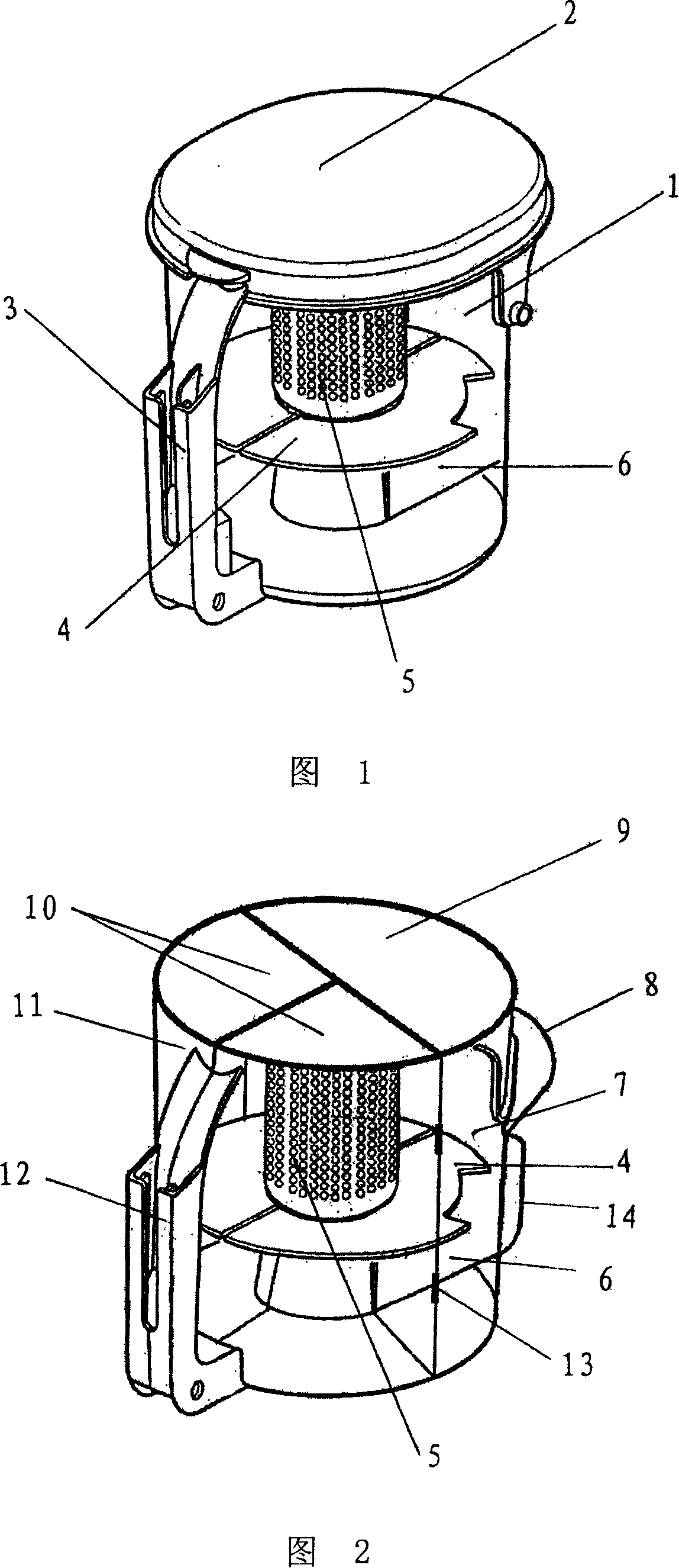
[0022] The specific embodiment of the present invention will be further described in conjunction with the accompanying drawings. Fig. 2 is a schematic diagram of the appearance and structure of the dust collecting barrel of the vacuum cleaner involved in the present invention. Fig. 3 is a schematic view of the front opening of the dust collecting barrel of the vacuum cleaner according to the present invention.

[0023] As shown in the figure, the dust collecting barrel of the vacuum cleaner involved is cylindrical, and is composed of a cylindrical barrel with an open front and a barrel top sealed on the barrel. The barrel is composed of a fixed barrel 7 and a barrel at the rear. The front part is formed with openings on both sides of the barrel 11, and the barrel top is composed of a fixed barrel top 9 at the rear and an open barrel top 10 at the front and is connected with the corresponding fixed barrel 7 and the open barrels on both sides of the front respectively. 11 combi...


PUM


Abstract

The vacuum cleaner dust-collecting barrel related by the present invention is formed from a cylindrical barrel body whose front end is opened and a barrel top set on the barrel body, said barrel body is formed from rear fixed barrel body and front barrel body whose front portion two sides are opened. The described barrel top is composed of rear fixed barrel top and front opened barrel top, and combined together with the correspondent fixed barrel body and front portion two-side opened barrel body respectively. One-edge of every side opened barrel body is hinged with one edge of said fixed barrel body is equipped with an air inlet and an air outlet, said air inlet is positioned in the upper portion of said fixed barrel body, and the air outlet is positioned in the lower portion of said fixed barrel body. Said invention can greatly raise its cdust-collecting efficiency.

Description

technical field [0001] The invention relates to a vacuum cleaner, in particular to a dust collecting bucket of the vacuum cleaner. Background technique [0002] The vacuum cleaner is a household appliance for indoor cleaning and hygiene, which is used to remove dust from the ground, carpets, walls, furniture and various gaps. Generally speaking, a vacuum cleaner mainly includes a suction device and a suction pipeline. The suction device mainly formed by a motor and a fan is arranged in the body. The suction pipeline includes a suction head and a suction pipe. The air port communicates with the air inlet of the fan inside the body through the telescopic pipe and flexible pipe of the suction pipe. When the vacuum cleaner is running, the motor drives the impeller of the fan to rotate at a high speed, exhausting the air in the vacuum cleaner, forming an instantaneous vacuum in the vacuum cleaner, and forming a relatively high negative pressure difference with the outside atmosp...

Claims


Application Information

Patent Timeline
IPC IPC(8): A47L9/10A47L9/00
Inventor 李艳君
Owner LG ELECTRONICS (TIANJIN) APPLIANCES CO LTD
Why Eureka
Try Eureka