


Quick Research
Generate reliable direction feasibility study reports for your R&D in just a few steps.

Technical Q&A
Discover and master advanced knowledge NOW. Basics, ideas, possibilities, all at once.

Find Solutions
As an expert in R&D theories, this can generate solutions to your technical problems instantly.

Evaluate Feasibility
Analyze your overall solution with one click, know your potential R&D risks in advance.

Monitor Landscape
Get weekly tech updates, stay abreast of the latest tech innovations and key insights.
Induction machine rotors with improved frequency response
A technology for induction motors and rotors, applied to asynchronous induction motors, electrical components, electromechanical devices, etc., to achieve the effects of reducing heat generation, improving transient response, and improving energy conversion efficiency
- Summary
- Abstract
- Description
- Claims
- Application Information
AI Technical Summary
Problems solved by technology
Method used
Image

Examples
Embodiment Construction
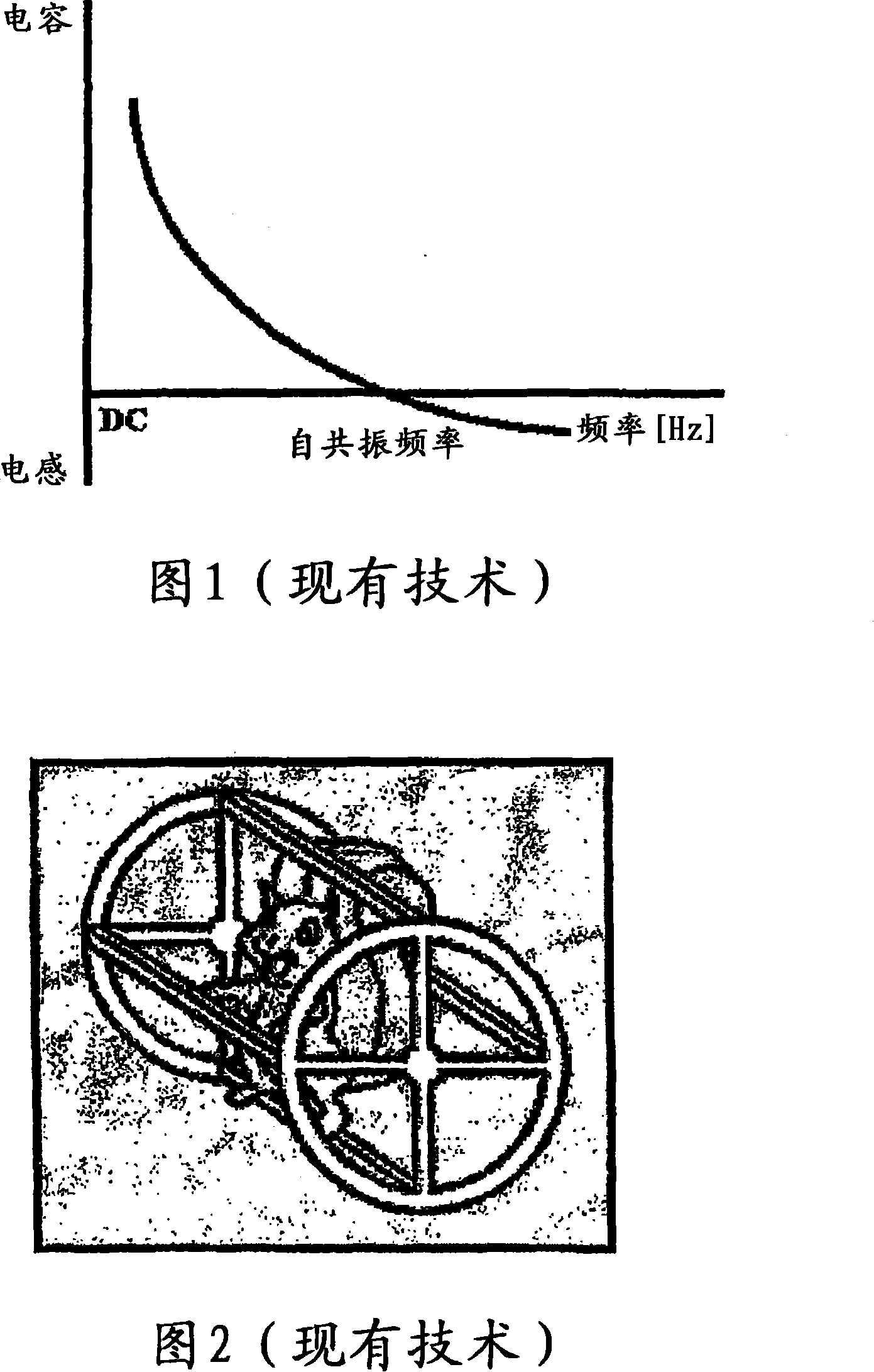
[0175] The rotor core and windings form an inductive circuit element. One or more capacitors may be added to the rotor to generally increase the power factor and thereby increase the power transfer and power conversion characteristics of the device. It is well known that capacitors and inductors can be combined in various LC configurations. These configurations may include series, parallel and mixed combinations of circuit elements.
[0176] When an induction motor is engaged, the rotor is generally stationary. At this moment, the stator and rotor are electromagnetically coupled to their maximum extent. Induction motors require a large magnetization VAR when engaged. As the rotor in an induction motor accelerates, the electrical frequency in the rotor decreases. To maintain a resonant or quasi-resonant circuit in the rotor as the rotor electrical frequency changes, a change in capacitance is required.
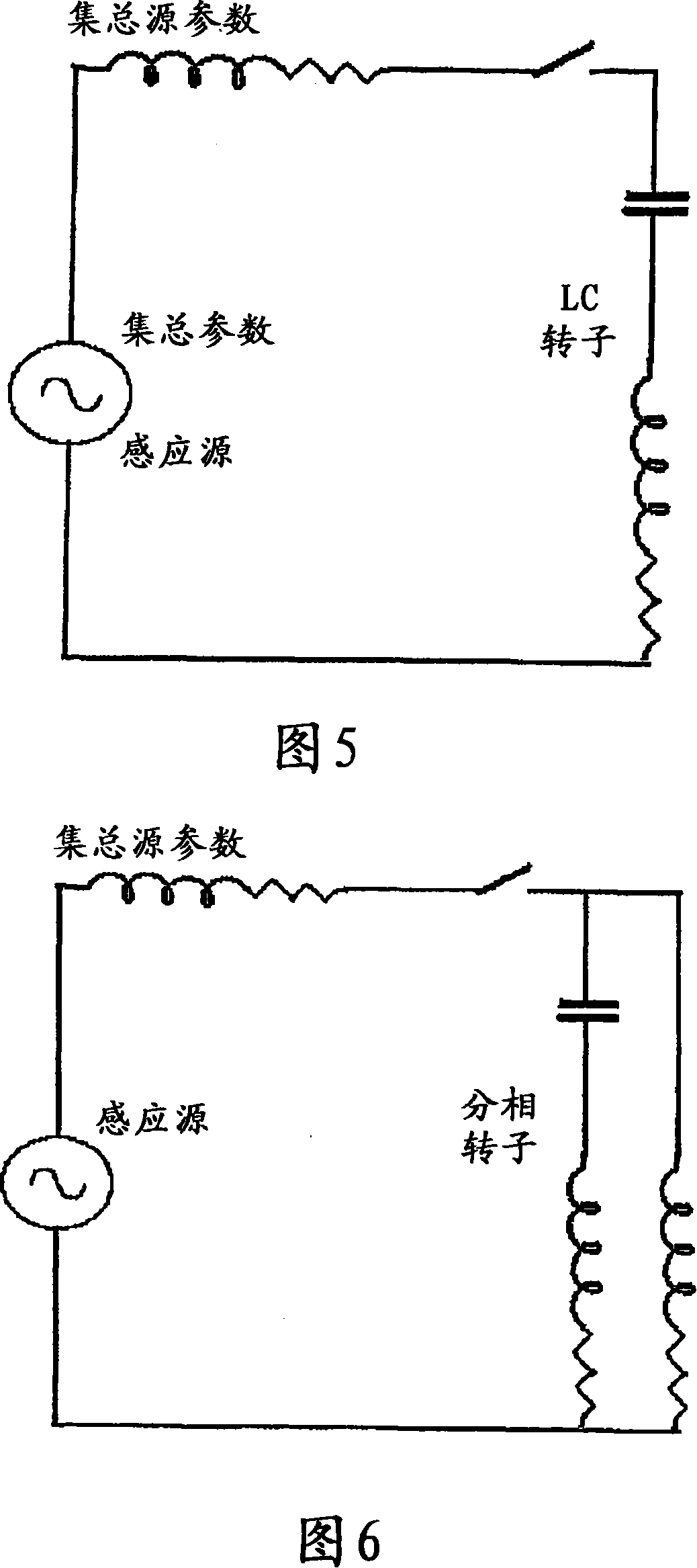
[0177] A simple LC rotor is shown in Figure 5, referred to as a serie...
PUM
 Abstract
Description
Claims
Application Information
 - R&D Engineer
- R&D Manager
- IP Professional
- Industry Leading Data Capabilities
- Powerful AI technology
- Patent DNA Extraction
Browse by: Latest US Patents, China's latest patents, Technical Efficacy Thesaurus, Application Domain, Technology Topic, Popular Technical Reports.
© 2024 PatSnap. All rights reserved.Legal|Privacy policy|Modern Slavery Act Transparency Statement|Sitemap|About US| Contact US: help@patsnap.com