Thin slide unit

A thin, sliding part technology, used in bearing elements, linear motion bearings, bearings, etc., can solve the problems of increased sliding resistance of sliding parts guide rails, short life of roll forming die, and reduced guide rail rigidity, etc. Small size, lower manufacturing cost, and the effect of reducing replacement frequency

Active Publication Date: 2008-03-19
THK CO LTD
View PDF0 Cites 3 Cited by
  • Summary
  • Abstract
  • Description
  • Claims
  • Application Information

AI Technical Summary

Problems solved by technology

However, when the guide claw is deformed as described above, since the guide claw contacts the side wall of the relief groove, there is a problem that the sliding resistance of the slider relative to the guide rail increases.
[0011] In addition, the relief groove is formed by roll forming at the same time as the ball rolling groove on the guide rail, but since the width of the relief groove corresponds to the thickness of the guide plate, it is extremely small, so the life of the roll forming die forming the relief groove is shortened. Extremely short, there is a problem that the manufacturing cost increases due to...

Method used


Image

  • Thin slide unit
  • Thin slide unit
  • Thin slide unit

Examples


Embodiment Construction

[0028] The thin sliding unit of the present invention will be described in detail below with reference to the drawings.

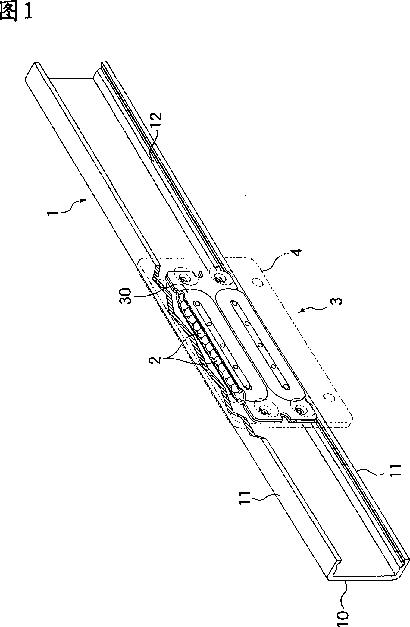
[0029] FIG. 1 is a diagram showing an example of a slide unit to which the present invention is applied. The sliding unit is composed of a guide rail 1 and a slider 3 assembled on the guide rail 1 via a plurality of balls 2 , and the slider 3 is configured to freely reciprocate along the guide rail 1 .

[0030] The guide rail 1 is formed in a channel shape in which a pair of side walls 11 and 11 stand up from a base 10 , and a space surrounded by the base 10 and the side walls 11 serves as a guide path for the slider 3 . On the inner side of each side wall 11 facing the guide way, a rolling groove 12 of the ball 2 is formed along the longitudinal direction of the guide rail 1, and these rolling grooves 12 face each other via the guide way. Each rolling groove 12 is formed in a so-called Gothic arch shape in which two ball rolling surfaces intersect at an a...


PUM


Abstract

A thin slide unit where an endless circulation path for balls is constructed by combining two ball plates having track-like ball grooves formed in them, wherein the balls are smoothly circulated in the unit constructed only by directly joining the two ball plates without use of a guide plate, thereby smooth reciprocation of a slider relative to a guide rail is realized. The endless ball circulation path of the slider is constructed by setting the two ball plates, having track-like grooves formed in them, opposite to each other and directly joining the ball plates together. When edge sides of the two ball plates are placed opposite to each other, a load opening for causing the balls in the endless circulation path to be in contact with a rolling groove of the guide rail is formed and, also, a scooping-up section for lifting the balls from the rolling groove to guide them into the endless circulation path is formed.

Description

technical field [0001] The present invention relates to a sliding unit which can move unrestrictedly along the guide rail through a plurality of balls assembled on the guide rail, which is used on a sliding part such as a copy machine, a protective cover of a working machine, and a weight door, and particularly relates to a sliding unit by A thin sliding unit is assembled in which a plurality of press-formed metal plates are applied to form the infinite circulation path of the balls on the sliding member. Background technique [0002] Conventionally, as a linear guide device utilizing the rolling motion of balls, there has been known a device consisting of a guide rail in which rolling grooves of balls are formed in the longitudinal direction, and a guide rail with a plurality of balls mounted on the guide rail and having an infinite loop of the balls. The sliding member of the road is constituted, and the sliding member freely reciprocates along the guide rail while the bal...

Claims


Application Information

Patent Timeline
IPC IPC(8): F16C29/06F16C33/60
CPCF16C29/0607
Inventor 粕川励齐藤洋宫崎英儿
Owner THK CO LTD
Why Eureka
Try Eureka